
The outflow hydrograph is iterative and is calculated based on equation 24, the routing coefficients (  ,
,  ,
,  ,
,  ) are re-calculated for every distance step ∆x and calculation time step ∆t.
Numerical Stability
∆t and ∆x are chosen internally by the model for accuracy and stability.
∆t is selected as the smallest of the following 3 rules:
- the user defined computation interval, DT,
- the time of rise of the hydrograph divided by 20,
- the travel time of the channel reach.
The model checks the difference between the computational time interval (DT) and the time increment of the inflow hydrograph (SDT). If DT is less than SDT, the inflow hydrograph will be interpolated. The calculation time step must be equal or less than the inflow hydrograph SDT.
A computational space increment ∆x can be equal to the length of the entire routing reach or to a fraction of that length. It is initially selected as the entire reach length. If the size of this space increment does not meet the accuracy criteria for flow routing given by Ponce and Theurer (1982), it is re-evaluated by subdividing the length of the routing reach into even subreaches that produce ∆x’s that satisfy the accuracy criteria.
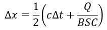 (32)
(32)
where,
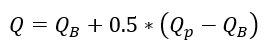 (33)
(33)
![]() = baseflow from the inflow hydrograph
= baseflow from the inflow hydrograph
![]() = peak flow from the inflow hydrograph
= peak flow from the inflow hydrograph
The Courant (C) number can be defined as:
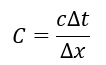 (34)
(34)
Main and overbank channel portions are separated and modelled as two independent channels. Right and left overbanks are combined into a single overbank channel.
Momentum at the flow interface between the two channel portions is neglected, and the hydraulic flow characteristics are determined separately, for each channel portion. At the upstream end of a space increment, the total inflow discharge is divided into main channel and overbank flow components. Each are then routed independently, using the previously described routing scheme. The flow redistribution between the main and overbank channels is based on Manning’s equation.