The drainage system component and the corresponding Visual OTTHYMO hydrologic objects are listed in Table 3-1. The hydrologic processes modelled are given below each hydrologic object, which are 1) flow generation, 2) flow routing, 3) flow separation and 4) flow merging. Each hydrologic object is represented with a unique icon.
1) Flow Generation Process: Generates flow from rainfall or snow melt on catchments. Flows from rural and urban catchments significantly differ due to decreased infiltration caused by urbanization. With the same amount of rainfall, the hydrograph from an urban catchment has larger and earlier peak flows and more runoff volume. Visual OTTHYMO provides one hydrologic object for urban catchments and three hydrologic objects for rural catchments. Often rural hydrologic objects in existing condition need to be converted to urban hydrologic objects for post-development condition.
2) Flow Routing Process: Routes flow through a certain structure. The hydrograph is usually changed (delay and attenuation). The structures supported are channels, reservoirs (ponds), and pipes. Ponds are important as they are usually required for a new development to control the flow to the allowable rates. Visual OTTHYMO can help size the ponds by determining the rating curve (storage-discharge relationship).
3) Flow Separation: Separates flow to multiple receiving structures such as flow diversion or catch basin. The latter is commonly used in new developments to have part of the runoff flow into the sewer system. In the planning stage, the number of catch basins can be estimated and Visual OTTHYMO can model it with minimal parameters.
4) Flow Merging: Merges flow from different sources to one single flow which typically happens at the confluence points. The outlet of the study area is usually a confluence point.
TABLE 3-1 DRAINAGE SYSTEM COMPONENT AND AVAILABLE VISUAL OTTHYMO HYDROLOGIC OBJECTS
| Drainage System Component | VO Hydrologic Object | Drainage System Component | VO Hydrologic Object |
|---|---|---|---|
Urban Catchment 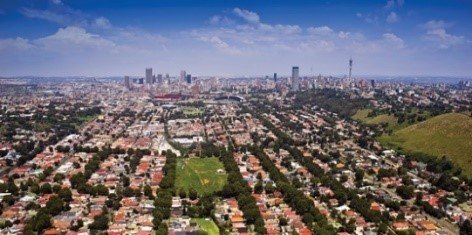 |
StandHyd (Flow Generation)  |
Channel, River 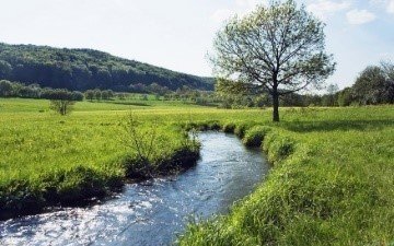 |
RouteChannel MuskingumCunge  ShiftHyd  CompoundChannel (Flow Routing) |
Rural Catchment 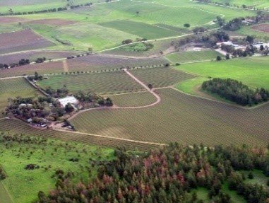 |
NasHyd WilHyd  ScsHyd (Flow Generation)  |
Reservoir, SWM Pond 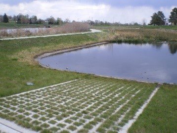 |
RouteReservoir |
Pipe 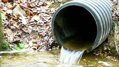 |
RoutePipe (Flow Routing)  |
Confluence 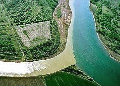 |
AddHyd (Flow Merging) |
Flow Diversion 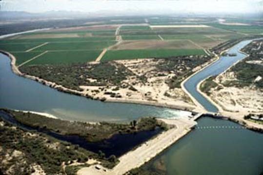 |
DivertHyd (Flow Separation)  |
Catch basin 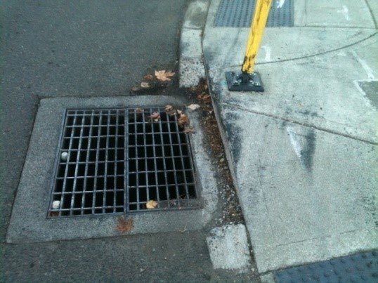 |
DuHyd (Flow Separation) |
Wetland 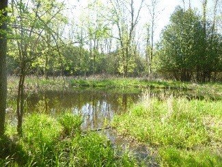 |
RouteWetland (Flow Routing) Only available in continuous mode |
Soakaway Pit 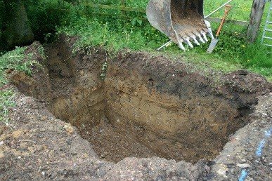 |
SoakawayPit (LID) |
Underground Chambers 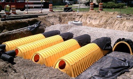 |
Underground Chambers (LID) |
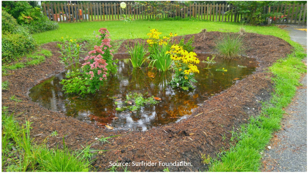 |
Rain Garden (LID) |
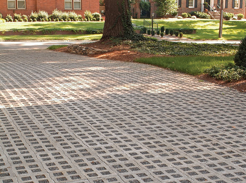 |
Permeable Pavement (LID) |
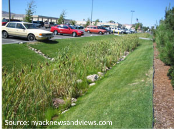 |
Enhanced Swales (LID) |
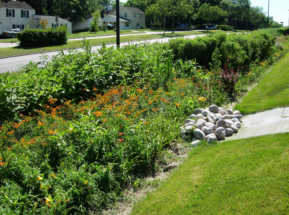 |
Bio retention (LID) |
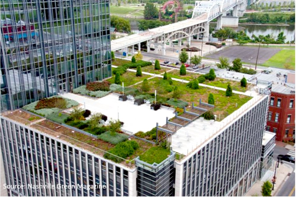 |
Green Roof (LID) |
 |
Filter |
Note that only NasHyd, StandHyd, AddHyd, RouteChannel, RouteReservoir, Route Wetland, SoakawayPit, Chambers, Pavement, Rain Garden, Green roof, Filter, Bio-retention and Enhanced Swales are available in continuous mode.


