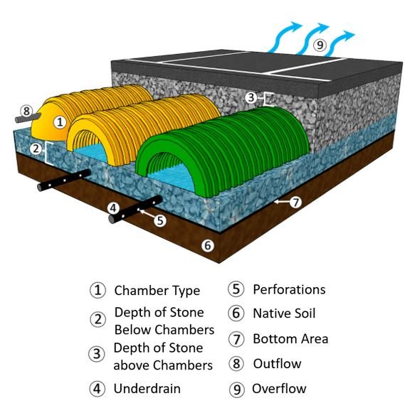
Underground storage chambers are typically designed to store larger volumes of water and are often used for quantity control. Underground storage chambers have large void spaces and typically have open bottoms allowing the system to infiltrate into the surrounding soils. VO offers generic LID options with standard default parameters and automatically calculates how much storage is required and provided. Certain brand LID manufacturers have also been listed with their unit design specifications. Underground storage chambers are designed with an overflow, an outflow, and an optional sub-drain feature. The diagram below shows key features of the underground storage chamber designs.
| Parameter Name | Description | Default Value |
|---|---|---|
| Chamber Selection | ||
| NUMBER OF CHAMBERS | Number of individual storage chambers used in design | 900 |
| BASE OF STONE ELEVATION | Base of stone/storage elevation | 100 |
| DEPTH OF STONE BELOW CHAMBERS | Amount of stone between the base of the systems and the in-vert of the storage chambers (mm) | 152 |
| DEPTH OF STONE ABOVE CHAMBERS | Amount of stone between obvert of the chamber and the top of the storage layer (mm) | 152 |
| MIN BOTTOM AREA | Bottom footprint area of the underground storage layer | 100 |
| MAX STORAGE VOLUME | Maximum volume provided with current system design. Max storage is automatically calculated with the input parameters (m³) | 978.51 |
| DEPTH-STORAGE RATING CURVE | Volume provided with current system design. Storage volume is automatically calculated with the input parameters (m³) | – |
| Initial Water Level | Depth of water in the storage layer at the start of a model run | 0 |
Copyright © 2025 Smart City Water
—
Powered by