
Soakaways typically consist of rectangular or circular stone-filled, geotextile-lined excavations that receive roof and walkway runoff via a perforated pipe inlet. The soakaway stores the water and allows it to infiltrate into the native soil.
In the soakaway model, we applied continuity equations to simulate two layers, including storage and native soil layers. The figure below is a soakaway model schematic.

SOAKWAY MODEL SCHEMATIC
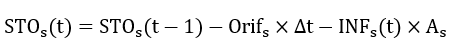
In storage layer, continuity equations can be written as follows:
 (10.13)
 (10.14)
 (10.15)
 (10.16)
 (10.17)
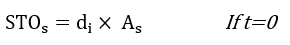
Where ![]() and
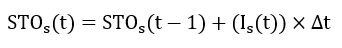
and ![]() (t) are the initial water stored volume and volume stored during the time step t in a soakaway (m³); di is initial water level of soakaway (m) and
(t) are the initial water stored volume and volume stored during the time step t in a soakaway (m³); di is initial water level of soakaway (m) and ![]() is soakaway bottom area (m²); Is is the inflow rate from the contributing catchment (m³/s); INFs is the infiltration rate (m/s), which is constant in a single even t and evaluated using a constant infiltration rate or Green-Ampt Mein-Larson (GAML) equation (Equations (10.1) and (10.2)) in a continuous model;
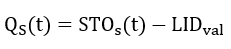
is soakaway bottom area (m²); Is is the inflow rate from the contributing catchment (m³/s); INFs is the infiltration rate (m/s), which is constant in a single even t and evaluated using a constant infiltration rate or Green-Ampt Mein-Larson (GAML) equation (Equations (10.1) and (10.2)) in a continuous model; ![]() is the underdrain flow rate (m³/s) and calculated by depth discharge curve or orifice equations. If volume of water stored (
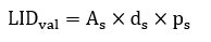
is the underdrain flow rate (m³/s) and calculated by depth discharge curve or orifice equations. If volume of water stored (![]() ) exceeds the LID design volume (
) exceeds the LID design volume (![]() ), the exceed volumes (
), the exceed volumes (![]() ) tend to make surface runoff.
) tend to make surface runoff. ![]() (m) is depth of the soakaway;
(m) is depth of the soakaway; ![]() is the effective porosity.
is the effective porosity.
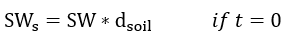
In the soil layer, initial soil water content is provided by users and a continuity equation is used to account water content of the soil base:
 (10.18)
 (10.19)
where ![]() is initial soil water content (m³/m³);
is initial soil water content (m³/m³); ![]() is the depth of native soil layer (m).
is the depth of native soil layer (m). ![]() is soil water content of the soil layer (m) and PC is the percolation rate in the soil base to ground water(m/s).
is soil water content of the soil layer (m) and PC is the percolation rate in the soil base to ground water(m/s).