
In VOSWMM, the overland flow is modelled by creating node and conduit on the ground. The hydraulics of those nodes and conduits are modelled by SWMM5 engine. In that way, the flow rate and depth can be obtained.
There are several rules recommended that users can follow when adding overland nodes and conduits.
- It is recommended to place overland nodes on the flow path
- It is recommended to make overland conduits match with flow path direction.
Regarding the locations of overland nodes, it is recommended to add overland nodes:
- at the starting point of the flow path
- when there is a catch basin / inlet along the flow path
- when there is a sag / pond area
- when there is a sewer manhole and at the curb of the road transect across the manhole
- on the crest of sag/pond area
- at a junction point when two flow paths meet
- when there is a change in cross sections
- when there is a change in slope
- when there is a change in roughness of the road / ground
- at the outlet point
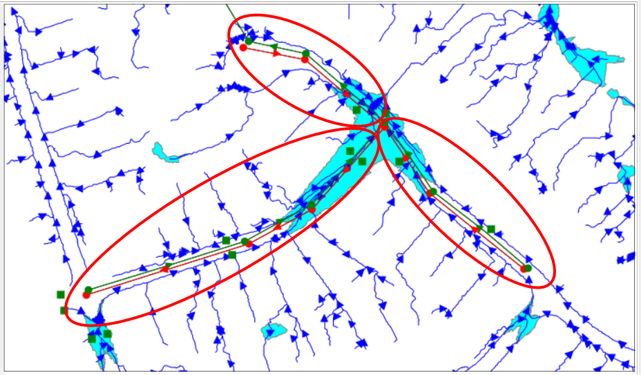
In this tutorial case, the overland flow path can be seen as three branches along with the minor system: the east branch, the south branch, and the north branch.
To add a major system, first change the default parameter of node and link. Click the Default Values button in the Simulation tab. In the pop-up window, navigate to the Nodes / Links tab and set the parameters as below.

Zoom into the upstream location, which is on the right bottom of the map, of the south branch. Drag and drop the Junction icon from the Tool Box to the Map canvas.

When the mouse cursor changes to the Edit mode, hover the mouse cursor to snap on the flow path. The snapped Vertex is shown in a red box.
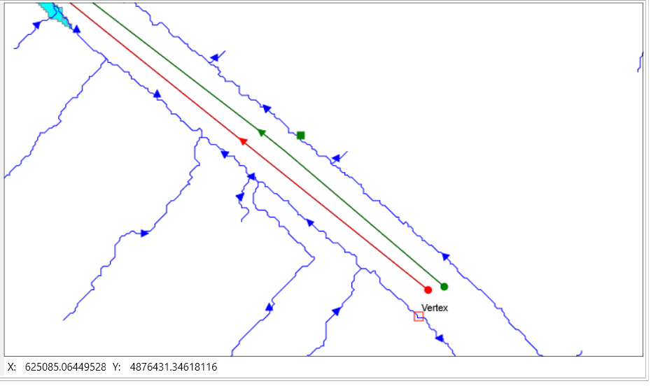
Left click the mouse to place the first node on the main stream of the flow path and close to the manhole.

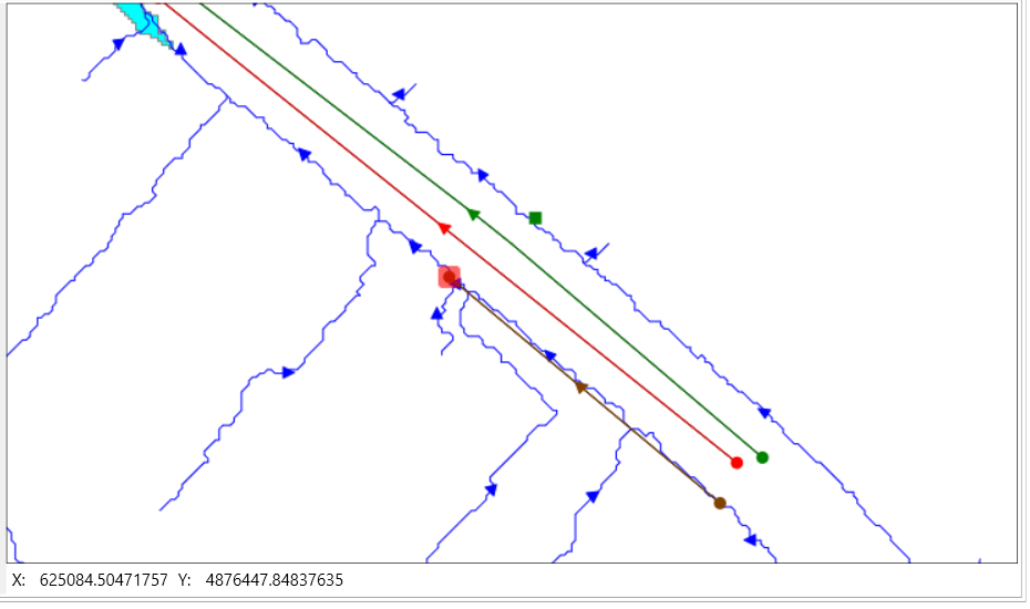
Move the map to down stream by holding and dragging the mouse middle wheel. Hold Ctrl key and place the second node on the main stream of the flow path and close to the catch basin. A conduit will be created automatically.
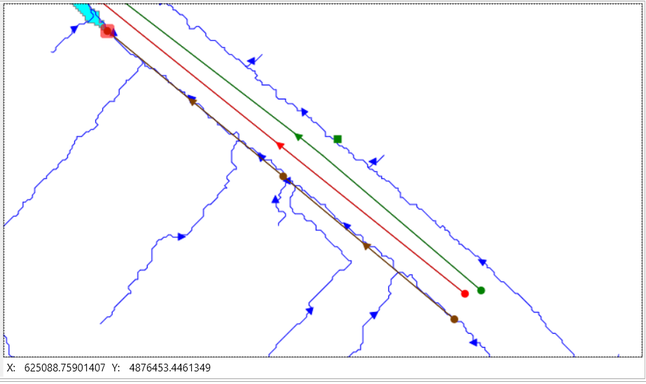
Following the same way to add the third major node on the sag area entrance, which also has two manholes nearby. A conduit will be created automatically by holding Ctrl key.
Following the same procedure to add nodes and links for the major system of the west and the north branches. The figure below highlights the major links in red. The major nodes are circled in black. For more details about the locations of the nodes and links, please refer to the solution model.
