
Designing SWMM detention ponds involves key elements: storage units, orifices, and weirs. These components are detailed below:
1. Storage Units: Storage units in SWMM are nodes, distinct from Example 2’s junction nodes. They utilize a Storage Curve to describe volume, allow specification of an Evaporation Factor, and necessitate defining a Maximum Depth.
- Storage Curve: This curve outlines a storage unit’s shape by detailing how surface area changes with water depth. SWMM integrates the curve to calculate stored volume based on depth. It can be defined as a functional equation or tabular data (area-depth pairs).
- Evaporation Factor: An Evaporation Factor = 1 facilitates surface evaporation, using evaporation data from SWMM’s Climatology Editor. A default 0 value means no evaporation consideration.
- Maximum Depth: Defining a maximum depth for storage units is crucial to avoid assuming a default depth of zero. If undefined, even with a storage curve or conduit connection, the model assumes zero depth. If the curve’s highest depth is below the maximum, the last curve area extends outward.
2. Orifices: SWMM’s orifice-type link models outlets on the side or bottom of storage units. Connecting an upstream node (storage unit) to a downstream junction via a conduit, orifices require specifications such as height above the unit’s bottom (invert offset), type (side or bottom), geometry (rectangle or circle with dimensions), and hydraulic properties (discharge coefficient, flap gate presence/absence for backflow prevention).
3. Weirs: SWMM’s weir-type link represents overflow structures at a storage unit’s top. Similar to orifices, the upstream node is the storage unit, while the downstream node connects to a conduit. Weir attributes encompass height above the unit’s bottom, type (transverse, V-notch, or trapezoidal), geometry, and hydraulic properties (discharge coefficients, end contractions, flap gate presence/absence for backflow prevention).
Note:
Within VOSWMM, the option to convert nodes or links into alternative node and conduit types is available. This conversion can be accomplished by adhering to the following instructions:
Convert a Node to a Storage Unit
1. Right-click the target node and select “Convert to…” from the pop-up menu.
2. Opt for “Storage Unit” from the ensuing sub-menu.

3. Click on the Properties for the new storage unit, assigning a new name (e.g. SU1), inheriting the node’s invert elevation and maximum depth.
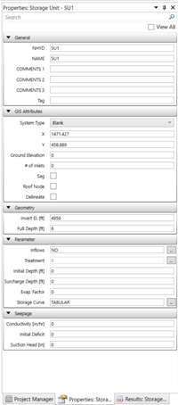
4. Configure additional storage unit properties, like the Storage Curve, as necessary.
For conduit-to-orifice conversion:
1. Right-click the conduit connected downstream of the storage unit, choose “Convert to…” from the pop-up menu.
2. Select “Orifice” from the sub-menu.

3. Open the Property Editor for the orifice, specifying dimensions, invert offset, and discharge coefficient.
To convert an outfall to a node:
1. When a storage unit (SU1) requires multiple orifices, direct orifice connection to an outfall (O1) isn’t feasible. In this scenario, the outfall must transform into a node (O1), necessitating the creation of a new outfall (O2).
2. Apply the same conversion process as mentioned earlier to transform the outfall into a node.