
Water Quality Treatment in LIDs
In line with Example 4, we treat the filter strip and infiltration trench LIDs as subcatchments to account for their combined impact on storm runoff, including pollutant reduction. While there aren’t well-established models for pollutant removal in these LIDs, we can use average removal rates based on field observations.
SWMM allows us to apply a constant BMP Removal Efficiency for specific pollutants in runoff from a particular land use. This reduces pollutant loads generated by that land use at each time step, including runoff from upstream areas. The LIDs introduced in Example 4 collect runoff but don’t generate pollutants themselves. To manage this conveniently, we introduce a new land use category called “LID” exclusively for these subcatchments, with a specific BMP Removal Efficiency for TSS.
Water Quality Treatment in Detention Ponds
SWMM models detention ponds as storage unit nodes. By adding Treatment Functions to these nodes, SWMM can lower pollutant concentrations in the pond’s outflow. In this example, we use an exponential decay function to mimic how solids settle in the pond during a 40-hour drainage period after a 2-hour fill-up, impacting TSS concentration ‘C’ at any given time ‘t’:
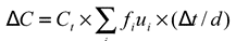
Here, ‘Ct’ represents the overall concentration of TSS particles at time ‘t,’ and ‘fi’ signifies the portion of particles with settling velocity ‘ui’. Since  is typically unknown, it can be substituted with a fitting parameter denoted as ‘k’ in the given equation:
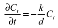
Please note that ‘k’ represents a particle’s settling speed within the total suspended solids in the solution and has velocity units (length per time).
Simulating Treatment within a Conveyance Network
In VOSWMM, you can apply water quality treatment at any node in the drainage system. To do this, simply access the node’s Property Editor, click the ellipsis button next to the Treatment property, and define treatment functions for the pollutants passing through that node.

The treatment function for a specific pollutant can take on one of the following formats:
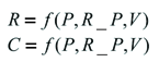
Here, ‘R’ represents the fractional removal, ‘C’ is the outlet concentration, ‘P’ stands for one or more concentrations denoted by pollutant names like TSS, ‘R_P’ signifies one or more pollutant removals (e.g., R_TSS), and ‘V’ encompasses one or more process variables such as FLOW (inflow rate into the node), DEPTH (water depth above the node invert), HRT (hydraulic residence time), DT (routing time step), and AREA (node surface area). Some treatment expression examples include:
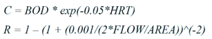
In a fractional removal expression, the new concentration at the node, ‘C,’ is calculated as Cin(1-R), with ‘Cin’ being the inflow concentration to the node. Additionally, when a concentration ‘P’ appears in an expression applied to a non-storage node, it equates to ‘Cin’ for the node. For a storage node, it refers to the current concentration ‘C’ within the storage unit.