
Engine Options ![]()

Click the Engine Options button. In the pop-up window, set parameters used by the SWMM5 engine.
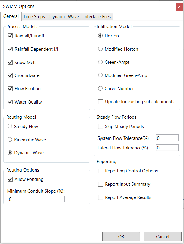
The General page in the Simulation Options dialog allows you to configure several key options for your analysis:
- Process Models: You can select which process models should be included in the analysis, such as Rainfall/Runoff, Infiltration, Snow Melt, Groundwater, Flow Routing, and Water Quality.
- Infiltration Model: This option lets you choose the default method for modeling rainfall infiltration into the upper soil zone of subcatchments. Options include Horton, Modified Horton, Green-Ampt, Modified Green-Ampt, and Curve Number. New subcatchments in the project will use the selected method as the default.
- Routing Model: You can determine the method used to route flows through the conveyance system. Choices include Steady Flow, Kinematic Wave, and Dynamic Wave.
- Allow Ponding: Enabling this option allows excess water to accumulate at nodes and be reintroduced into the system when conditions allow. To enable ponding at a specific node, you need to specify a non-zero value for its Ponded Area attribute.
- Minimum Conduit Slope: This setting establishes the minimum allowable slope (%) for conduits. By default, if set to zero, no minimum slope is enforced, although VOSWMM has a lower limit on elevation drop of 0.001 ft (0.00035 m) when calculating conduit slopes.
The Time Steps page in the Simulation Options dialog allows you to configure various time step settings for your simulation:
- Reporting Time Step: Specify the time interval for reporting computed results.
- Runoff – Wet Weather Time Step: Set the time step for computing runoff during rainfall, ponded water, or when LID controls are active.
- Runoff – Dry Weather Time Step: Define the time step for runoff computations during dry periods with no rainfall, no ponded water, and dry LID controls. Must be greater or equal to the Wet Weather time step.
- Control Rule Time Step: Determine the time step for evaluating Control Rules. The default is 0, meaning controls are assessed at every routing time step.
- Routing Time Step: Specify the time step for routing flows and water quality constituents through the conveyance system. Note that Dynamic Wave routing requires a smaller time step than other flow routing methods.
- Steady Flow Periods: This section defines criteria for identifying steady flow periods when hydraulic conditions in the system are not changing. Steady flow is recognized when inflow and outflow differences are below specified tolerances. You can choose to skip steady flow periods to speed up simulations, though this may reduce accuracy.
The Dynamic Wave page in the Simulation Options dialog allows you to configure parameters specifically for dynamic wave flow routing computations. These settings do not apply to other flow routing methods:
1. Inertial Terms: You can choose how to handle inertial terms in the St. Venant momentum equation:
- KEEP: Maintains full value under all conditions.
- DAMPEN: Reduces terms as flow approaches criticality and ignores them when supercritical.
- IGNORE: Eliminates terms, essentially creating a Diffusion Wave solution.
2. Define Supercritical Flow By: Selects the basis for determining when supercritical flow limits maximum flow to normal flow. Options include slope, Froude number, or both.
3. Force Main Equation: Choose the equation to compute friction losses during pressurized flow for conduits with a Circular Force Main cross-section. Options are Hazen-Williams or Darcy-Weisbach.
4. Surcharge Method: Decide how to handle surcharge conditions. Options are Extran (Surcharge Algorithm) or Slot (Preissmann Slot).
5. Variable Time Step: Check the box to use an internally computed variable time step, and select an adjustment factor. The time step satisfies the Courant condition and should typically be around 75% of the fixed time step.
6. Minimum Variable Time Step: Specify the smallest allowed time step when using variable time steps. The default is 0.5 seconds.
7. Time Step for Conduit Lengthening: Set the time step for artificially lengthening conduits to meet Courant stability criteria under full-flow conditions. A value of 0 means no conduits are lengthened.
8. Head Convergence Tolerance: Specify the maximum difference in computed heads between successive trials for convergence within a time step. Default is 0.005 ft (0.0015 m).
9. Minimum Nodal Surface Area: Define the minimum surface area used at nodes when computing water depth changes. Default is 12.566 sq. ft (1.167 sq. m).
10. Maximum Trials Per Time Step: Determine the maximum number of trials used in the iterative method for computing a dynamic wave hydraulic solution within each time step.
11. Number of Parallel Threads to Use: Select the number of parallel computing threads on multi-core processors. Default is 1.
The Interface Files page in the Simulation Options dialog is for specifying interface files used or saved during the simulation. This page has a list of selected files and three options:
- Add: Adds a new interface file specification to the list.
- Edit: Edits the properties of the currently selected interface file.
- Delete: Removes the currently selected interface file from the project (but not from your hard drive).
When you click the Add or Edit buttons, an Interface File Selection dialog opens, allowing you to specify the type of interface file, whether it should be used or saved, and its name.