
Direct Inflow
The “Direct” page in the Inflows Editor dialog is a tool used to define how external flow and water quality enter a node in a drainage system over a specific period. It involves two main components:
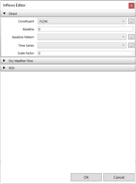
- Baseline Component: This represents a constant or steady component of the inflow. For instance, it could signify a constant flow rate or a fixed pollutant concentration. You can assign a value for this baseline component.
- Time-Varying Component: This part of the inflow can change over time. You have two options here:
- Baseline Pattern: An optional time pattern that adjusts the baseline inflow. It can be set to change on an hourly, daily, or monthly basis.
- Time Series: A named time series that describes how the inflow varies with time. For example, it can represent how flow rates or pollutant concentrations change over hours, days, or months.
You also have control over a few other settings:
- Scale Factor: This factor multiplies the values in the time series, allowing you to adjust the magnitude of the time-varying component without modifying its shape.
- Inflow Type: For pollutants, you specify whether the inflow data represents a concentration (mass/volume) or a mass flow rate (mass/time).
- Units Conversion Factor: This factor is used to convert pollutant mass flow rate units in the time series into concentration mass units per second.
Note:
Direct Inflow = (Baseline Value * Baseline Pattern) + (Time Series Values * Scale Factor)
Dry Weather Inflow
The “Dry Weather” page in the Inflows Editor dialog is used to specify a continuous source of dry weather flow entering a node in a drainage system. It provides options for defining the properties of this inflow:
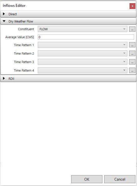
- Constituent: You can select the constituent for which you want to specify the dry weather inflow. It can be either “FLOW” (representing the flow of water) or one of the project’s specified pollutants.
- Average Value: This field allows you to specify the average or baseline value of the dry weather inflow for the chosen constituent. You should provide this value in the relevant units, such as flow units for water flow or concentration units for pollutants. If there’s no dry weather flow for the selected constituent, you can leave this field blank.
- Time Patterns: You can assign time patterns to the dry weather flow to make it vary periodically. These time patterns can be defined for different months of the year, days of the week, and times of the day, both on weekdays and weekends. You can either enter the name of a time pattern or select a previously defined pattern from a dropdown list. Up to four different types of time patterns can be assigned to control the variation of dry weather flow.
Note:
DWF = Average Value * Time Pattern1 * Time Pattern2 * Time Pattern3
RDII Inflow
The “RDII Inflow” page in the Inflows Editor dialog is used to specify RDII for a particular node. This page includes the following input fields:
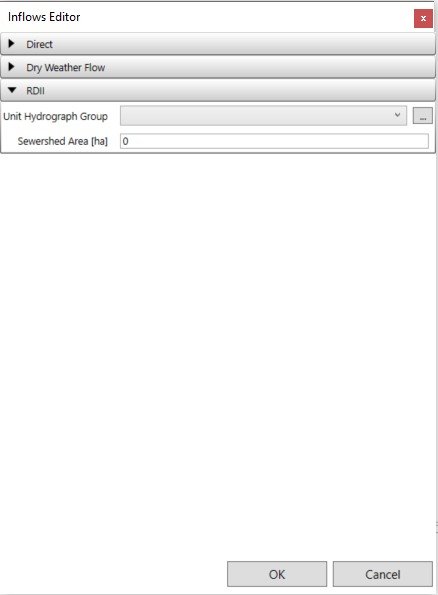
- Unit Hydrograph Group: You can select from a dropdown list the Unit Hydrograph group that applies to the node in question. Unit hydrographs within this group, combined with the group’s assigned rain gage, are used to generate a time series of RDII inflows per unit area throughout the simulation period. Leaving this field blank indicates that the node does not receive any RDII inflow. You can also click the edit button to access the Unit Hydrograph Editor for the specified UH group.
- Sewershed Area: Here, you enter the area in either acres or hectares that make up the sewershed contributing RDII to the node in question. It’s important to note that this area typically represents a localized portion of the subcatchment area that contributes surface runoff to the node.