Figure 2-4 illustrates the layout of the runoff conveyance system intended for incorporation into the developed site. This system encompasses 7 grass swales, 3 culverts, and a single street gutter. The primary aim here is to assess discharges at the site’s outlet, rather than design the entire drainage system. Therefore, only the main surface conduits responsible for routing runoff to the outlet within the combined model will be addressed. These conduits will intentionally be oversized to ensure smooth conveyance of all runoff to the outlet, preventing site flooding (a detailed analysis of flooded junctions and surcharged pipes is available in Example 7). The model’s foundation comes from the Example1-Post.inp input file, originating from Example 1.
Figure 2-4

In Example 1, subcatchment dimensions were tailored for accurate overland flow representation. All subcatchments directly connected to the study area’s outlet, excluding channel flows. For this example, subcatchment characteristics remain consistent, while conduits simulating channeled flow across the site will be integrated.
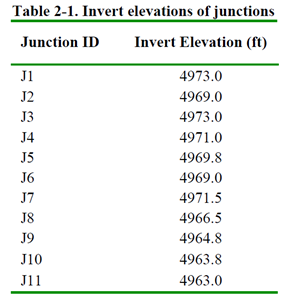
Defining the conveyance system starts with pinpointing node positions (or junctions). Nodes are vital where runoff enters the system, channels converge, or where there are significant slope or cross-section changes. Nodes are also crucial for locations with weirs, orifices, pumps, and storage (as in Example 3). Node locations are shown in Figure 2-5, labeled J1 to J11, with invert elevations detailed in Table 2-1.

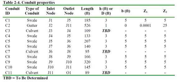
Continuing, feeder channels C1, C2, and C6 are introduced, conveying runoff into the main drainage path across the undeveloped park area. C1 is a grass swale directing S1’s runoff, C2 serves as a gutter for S2’s runoff towards culvert C11, discharging at site outlet O1, and conduit C6 conveys runoff from S4 into culvert C7. Channel bed elevations match junction invert elevations.
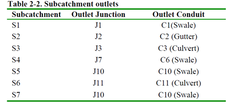
Finally, conduits C3 to C11, constituting the main drainage route, are defined. Similarly, these conduits connect to their end nodes without vertical offset. S3 to S7 subcatchments drain to various points along the main drainage channel. For instance, S3 drains to C3 at the start, S4 to swale C6 connecting to second culvert C7, S7 and S5 to J10, and S6 directly to final culvert C11. Table 2-2 summarizes outlet junction and conduit for each subcatchment.
Note, this example’s conveyance system (Figure 2-5) excludes street gutter storage and transport. For simplicity, we focus on primary drainage channels within the site.
System Properties
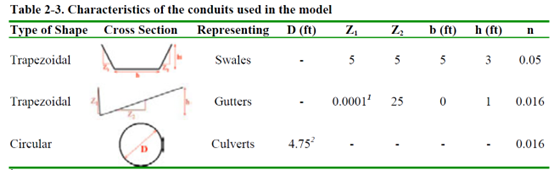
Conduit and junction properties can now be assigned. Table 2-3 presents the cross-sectional shapes for three conduit types. Swale characteristics adhere to UDFCD Manual (2001) recommendations, while gutter properties align with standard design practices. Culvert diameters, accommodating the 100-year storm runoff, will be determined later. In Table 2-4, SWMM properties are allocated. For all surface channels, junction maximum depth is set at zero, determining depth based on conduit elevation. Junction flooding occurs when channel capacity is exceeded. The outfall node O1 is designated a free outfall with an elevation of 4962 ft. The resulting SWMM input file is named Example2-Post.inp.