
The SWMM model for the undeveloped site is depicted below. It consists of a single Subcatchment S1 whose runoff drains to Outfall node O2. Note that the undeveloped site contour map has been used as a backdrop image. The scenario name is undeveloped.

Utilizing a Backdrop Image in VO SWMM
To help facilitate the placement of drainage-system objects, SWMM can utilize an image as a backdrop behind a project’s study area map. This image is typically a site map of some kind with known dimensions. Any bitmap image file (BMP extension), JPEG image file (JPG or JPEG extension) can be used as a backdrop. These images would typically come from a CAD or GIS drawing of the site or perhaps from an electronically published or scanned topographic or street map.
To add the background image, right click on the empty space on the Schematic view to open context menu. Navigate to Background -> Change Background. The background for undeveloped site could be found at “…\backgound\undeveloped site.jpg”.
Create Catchment and Outfall
To create catchment and outfall on canvas, find the command type in the Toolbox and drag and drop the command to the Schematic view on desired location. To create the connection, move the mouse on top of Subcatchment S1, click and hold the mouse, drag to Outfall node O2 and release the mouse.
Subcatchment Properties
According to the site’s contour map, its topography is fairly homogenous and no well-defined channels exist within the basin which means that mainly overland flow takes place. There are no roads or other local impervious areas and the type of soil is similar throughout the watershed (Sharpsburg silt loam). Therefore, no disaggregation is required based on the spatial distribution of catchment properties. The single sub-catchment S1 drains to the free outfall node O2 whose elevation is 4967 ft.
The area is not the entire pre-development natural catchment. It has been bounded by the post-development roadways to come so that comparisons between the two conditions (developed and undeveloped) can be made.
The properties assigned to the single sub-catchment S1 are summarized in Table 1-1.
Their values were developed on the basis of the undeveloped site being primarily pasture land containing a silt loam soil. Parameter values for this soil type can be found in the SWMM User’s Manual and the UDFCD Guidance Manual.
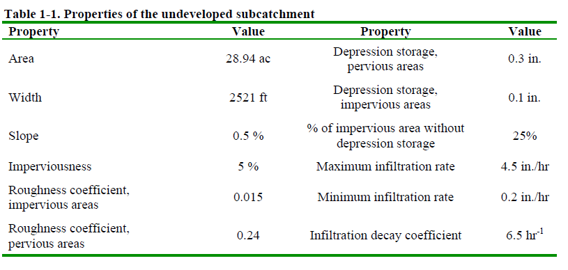
The sub-catchment’s area was determined using SWMM’s Auto-Length tool. The sub-catchment width was arrived at by first assuming a maximum overland-flow length of 500 ft, as recommended for undeveloped areas. By the time runoff has traveled this distance it has consolidated into rivulets and therefore no longer behaves as overland flow over a uniform plane. Based on this assumption, the sub-catchment was divided into subareas with flow-path lengths of 500 feet or less. Figure 1-5 shows that there were three such areas whose flow-path lengths are each 500 ft. Thus, the average flow length is also 500 ft. When the total sub-catchment area of 28.94 acres (1,260,626 ft2) is divided by the average flow length the resulting sub-catchment width is 2,521 ft. The average slope of the sub-catchment was derived from the area-weighted average of the slopes of the three sub-areas that comprise the overland flow paths as shown in Figure 1-5 and Table 1-2. Its value is 0.5.


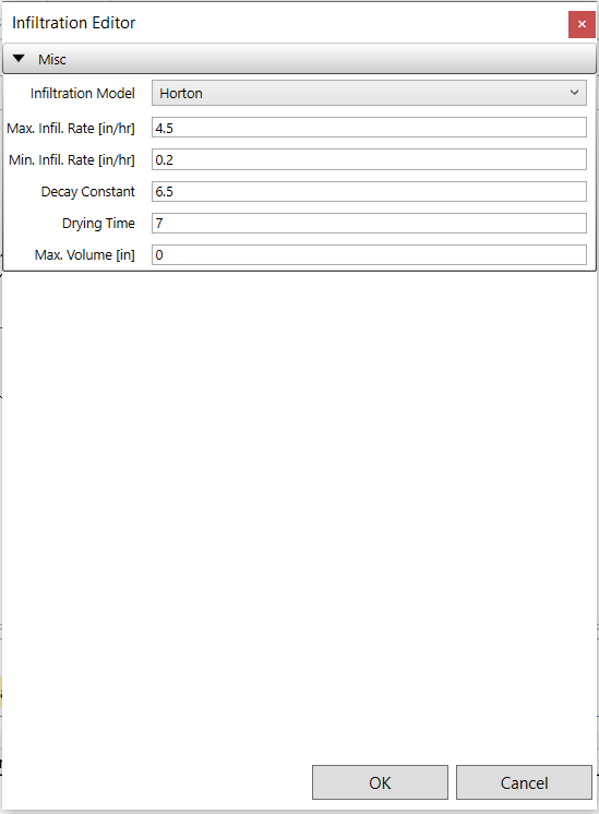
The Horton method was selected as the infiltration model for this analysis. The values assigned to its parameters are typical of those for a silt loam soil as found in this watershed and are listed in Table 1-1. It is strongly recommended to use any available site-specific data from the study area BEFORE relying on values from the literature.
Add Design Storm to Resource Library
There design storms are prepared in the subfolder design storm. To add them to the resource library, create a top group named “Post-development Runoff” and load all three design storms files with “Add Design Storm – From Multiple Storm Files”. To create simulation runs to all three design storms, select “Add Design Storms to Project” option.

Analysis Options
Table 1-3 shows the analysis options used to run the model.
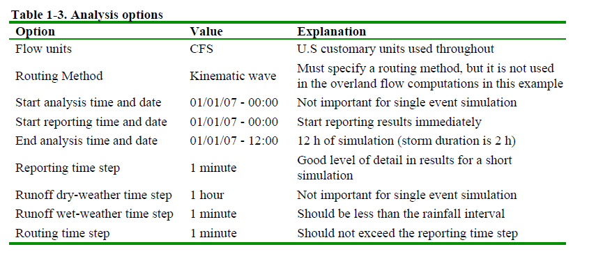
These analysis options could be setup in Properties tab of scenario, Run Option and SWMM Option window.


Run Simulation
To run the simulation for all design storms, click the Run button in the Simulation toolbar to open the Batch Run window.
