
Drawing a hatch.
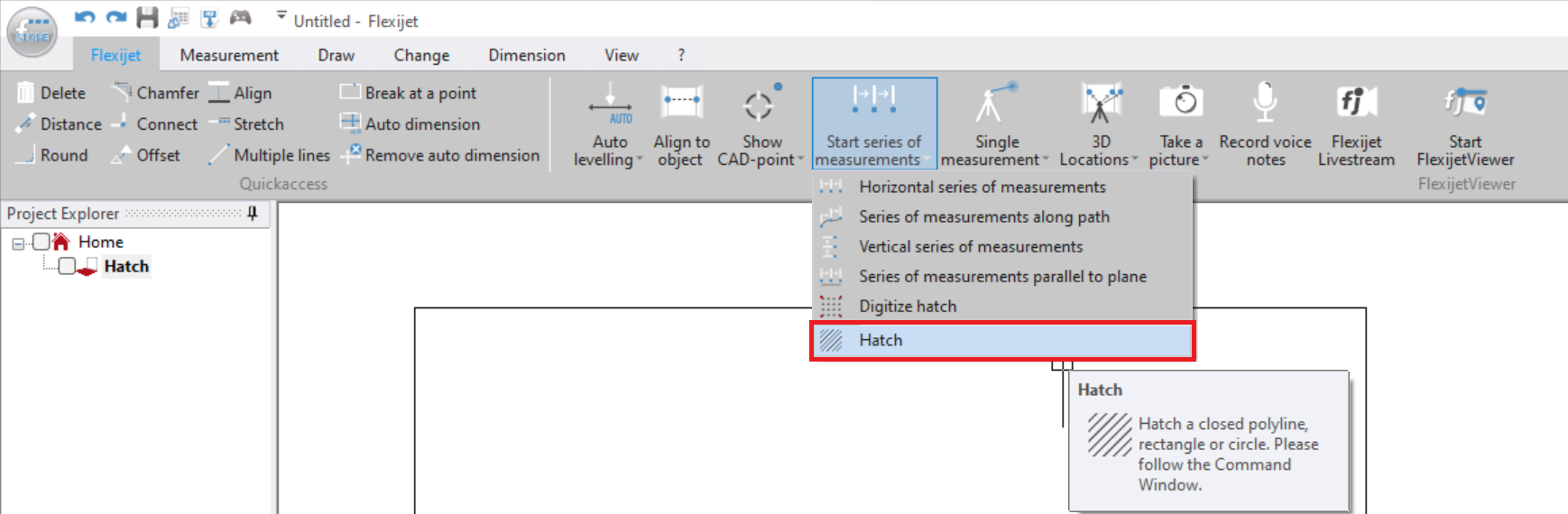
- Select Hatch from the drop down section of ‘Start Series of Measurements’ on the ‘Flexijet’ ribbon.
![]()
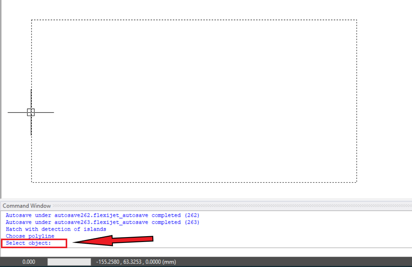
- As prompted in the Command Window, select the object to be hatched. In versions 3.3 and later, the object only needs to be a complete shape – it does not need to be joined into a Polyline. After selecting the bounding object, You may also select closed objects (polylines or rectangles) within the original hatched area to be ignored, such as a cutout.
![]()
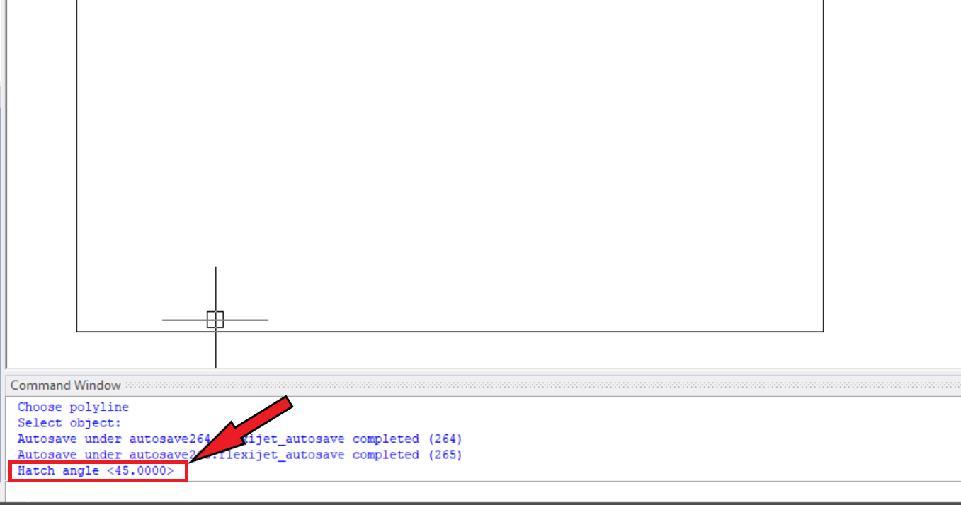
- Follow the Command Window prompts to set the Angle of the hatch (45deg by default).
![]()
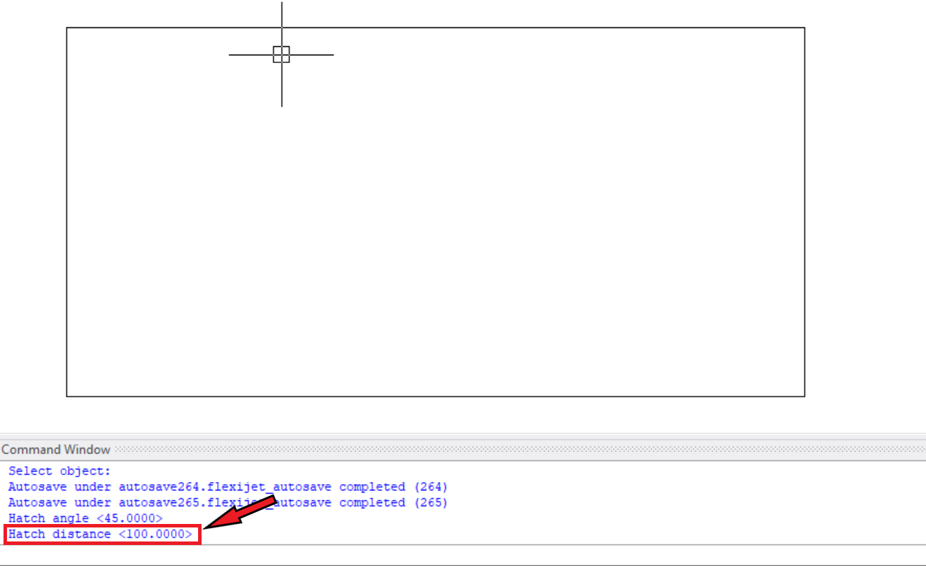
- Then, set the distance of the hatch. The ‘Digitize Hatch’ command will measure at these intersections.
![]()
![]()

Digitizing a hatch.
The Digitize Hatch command will measure the distance of all the intersecting points within a hatched area. For example a hatch in a rectangular area on a wall can be measured to determine high and low points in order to effectively clad with glass or stone.
Follow these instructions to digitize a hatch.
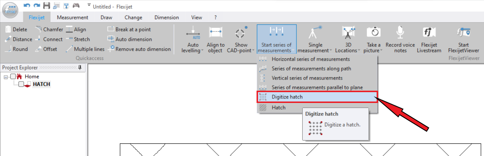
- From the ‘Flexijet’ Ribbon, select Digitize Hatch from the ‘Series of measurements’ drop-down menu.
![]()
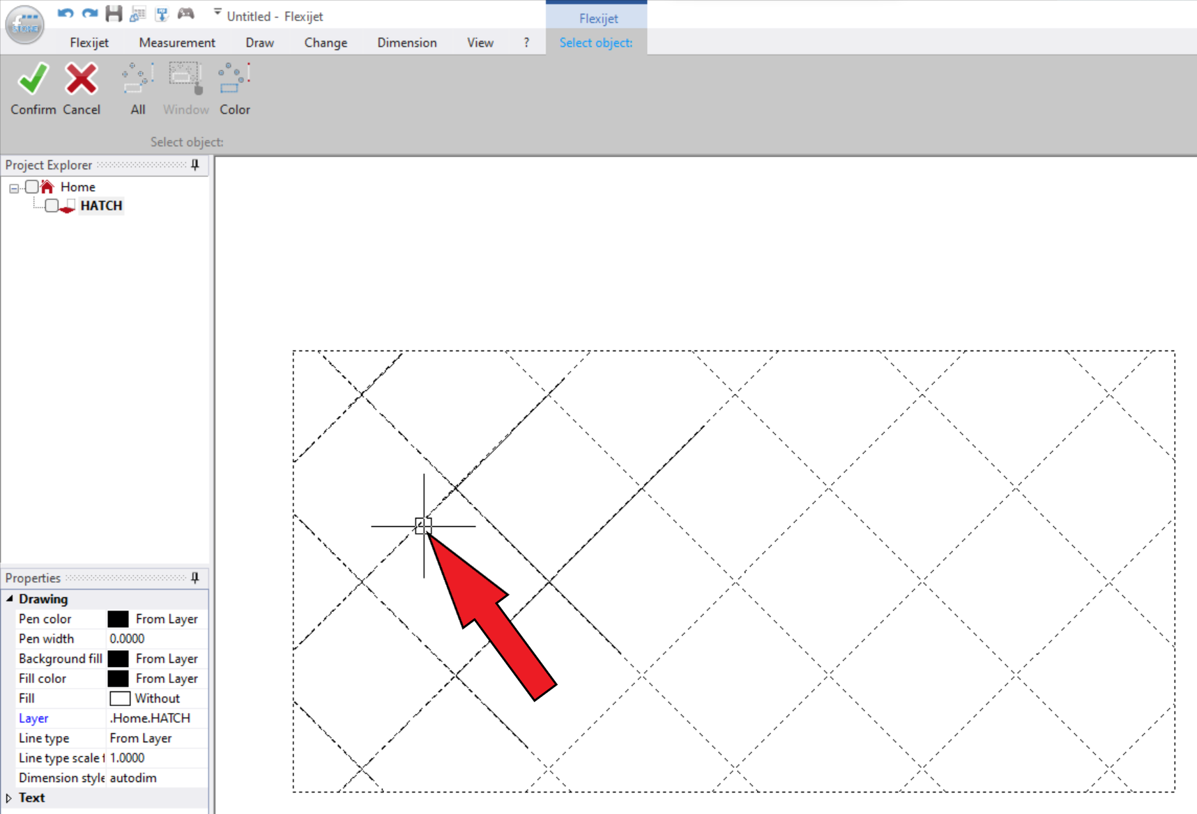
- Select the hatch that you want to digitalize.
![]()
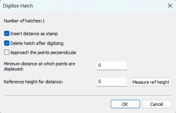
- From this menu, you can select multiple options.
![]()
- The Flexijet will now measure all the points on the grid, moving through the points sequentially until it has completed all the measurements.
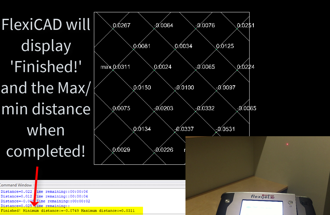
- When completed, FlexiCAD will display ‘Finished’, followed by the minimum and maximum distances measured.
For version (3.2.7.0) and earlier.
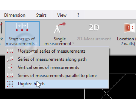
- From the ‘Flexijet’ Ribbon, select Digitize Hatch from the ‘Series of measurements’ drop-down menu.
![]()
- Follow the Command Window prompts to Select the Object (hatch) to be digitized (and press enter to confirm), set a value for Distance (if exceeded points are shown, usually ‘0’) or press ‘Enter’ to use the default value, and then decide whether to Insert distance Stamp by inputting ‘1’ for Yes or ‘0’ for No. This determines whether to display the distance numbers.
- Then, you will be prompted to set a reference point with the Flexijet for the distances to be measured, from which the point distances are measured. This is the ‘base’ value for the distance grid to be displayed. Recommended: If you want your scan to be relative to your current plane, set this by clicking an element in your drawing that is set to this plane. Or, you can measure a particular point as a reference.
- The Flexijet will now measure all the points on the grid, moving through the points sequentially until it has completed all the measurements.
- When completed, FlexiCAD will display ‘Finished’, followed by the minimum and maximum distances measured.
![]()
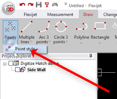
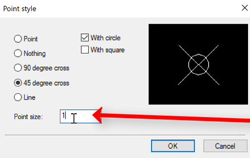
- Change the point size to better view the color-coded elevation map by going to ‘Point style’ on the ‘Draw’ ribbon. Change the point size to be larger in order to view the points. If working in inches, a value of 1 is often appropriate.
![]()
![]()
![]()

Note: in earlier versions of FlexiCAD/Flexijet Stone, the ‘Hatch’ tool may only function with closed contours such as polylines. In this case, use the ‘Single Elements to Polyline’ tool found under the ‘change’ ribbon to create a polyline first, which can then be hatched.
Watch the Video Tutorial!
Feedback
Copyright © 2025 Flexijet GmbH
—
Powered by 
Post your comment on this topic.