For users of FlexiCAD/Flexijet Stone 3.0.14 and earlier, please use the following instructions:
- Ensure that the repositioning points are placed as far apart as possible, ideally on opposites of the Flexijet, and at as close to level with the laser as possible, and that they will be visible from the new position as well.
- Select the root Project folder (3D folder)
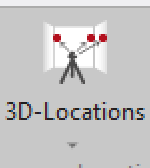
- From the ‘Flexijet’ ribbon, select ’3D Locations’
![FlexiCAD 3D Locations button]()
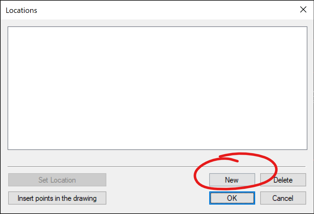
- From the menu, select ‘New’
![FlexiCAD Locations window]()
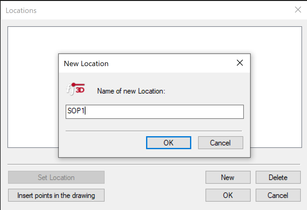
- Name the new location(set of points). Note: we are creating the points that will be used for repositioning, not the physical location of the Laser. You may also think of this as a Set of Points, and name it SOP1, for example
![FlexiCAD locations name of new location SOP1]()
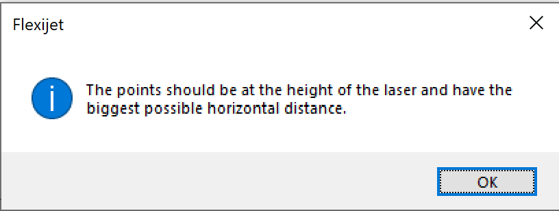
- A message will appear reminding that the points should be at the height of the laser and have the biggest possible horizontal distance. Click ‘OK’ to proceed.
![FlexiCAD locations warning points spread apart]()
- Now, measure your points. You may use the Flexijet Location stickers as required. Only 2 points are required to reposition, though more can be created at this point (such as for multiple repositions). Note the order in which the points are measured. The Flexijet will click 5 times to measure each point, then a ringing sounds will play, and the command window will prompt you to measure the next point.
- When you have measured the location points you wish to measure, end the function.
- Move the Flexijet laser to the new position, and ‘Autolevel’ the flexijet in its new position. The warning about losing the drawing reference will pop up – Click ‘OK’ to proceed, as we have moved the Flexijet.
- Now, click on the ’3D Locations’ button.
![FlexiCAD 3D Locations button]()
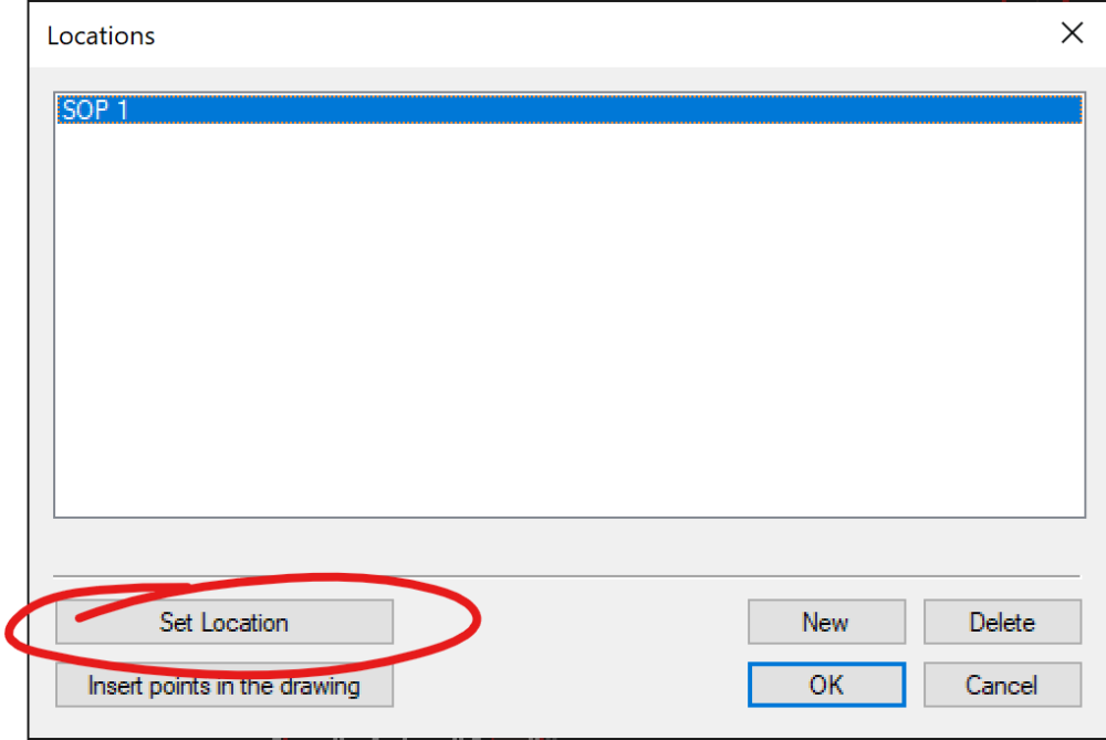
- Select the Location points/series of points that you created by measuring, and click ‘Set Location’
![]()
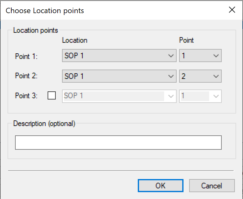
- Select the points you wish to use to reposition. You may choose up to 3 points, from multiple sets of points. For simple relocation with 2 points, simply use the 2 points as selected by default by clicking ‘OK
![Flexicad Choose location points]()
- A Warning message reminding that you must Auto-level the Flexijet before proceeding will appear. If you Auto-Levelled the Flexijet in its current physical location, click ‘OK’ to proceed’
- Now, re-measure the points in the same order as before.
- When you have successfully repositioned, you may check the accuracy of the repositioning by projecting some points using the Show CAD Points function. Be sure to select the appropriate 2D folder to measure before continuing. FlexiCAD will show the location as active in green in the bottom Left hand corner of the screen.
!NOTE: After repositioning, the Horizontal Alignment tool will behave differently! Recommended not to use the the Horizontal Alignment tool after repositioning, during measurement.



Post your comment on this topic.