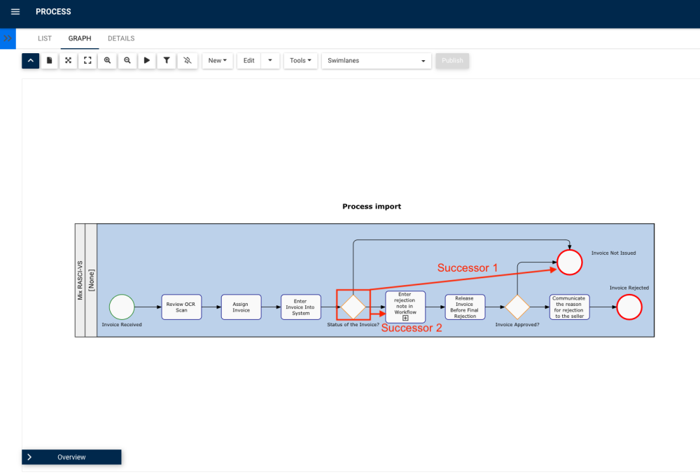
Organizations can create complex EPC maps from Parser by simply identifying their successor flow object activity and subsequent pathways, just as you would when using the EPC Process Modeler.
To create a complex graph from the Parser, please follow these steps and rules:
1. Upload your document and define the template.
2. If you are using a table, start by defining the header.
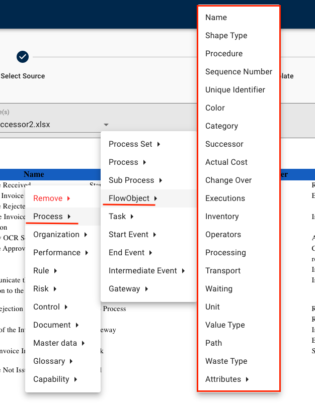
3. Click on the desired object -> Process -> Flow Object
| Tag | Meaning |
|---|---|
| Name | Name of the flow object |
| Shape Type* | Flow object’s shape type: Start, Task, Intermediate, Gateway or End |
| Procedure | Description (in EPC) of the flow object |
| Sequence Number | Flow object’s sequence number |
| Unique Identifier | Flow object’s unique identifier (ID) |
| Color | Flow object’s color in the EPC map (e.g #002d56) |
| Category | Flow object’s category |
| Sucessor* | Tag used to define which object(s) will follow the one you are currently tagging in the map. An example will be given below. |
| From Actual Cost to Waste Type | Flow object’s Analysis attributes |
| Attributes > | User-defined attributes available in your EPC system for flow objects |
* Important tags used for multi-path maps
How do I use multiple successors for Gateway flow objects?
As for gateways, you can define more than one successor flow object, which will create subsequent pathways in your graph, just as you would when using the EPC Process Modeler.
In your Word or Excel document, separate your successor flow object names with a line break or semicolon ( ; ), like so:
Full workflow for tagging flow objects in your document:
Result in EPC’s process module:

Additional Rules
- If the successor activity is not defined it will automatically use the order defined in your document
- If the flow-object type not defined, it will automatically use ‘TASK’
Need more help with this?
Visit the Support Portal


