The Manage->Fixture Profile Library allows new fixture profiles to be created, and existing fixture profiles to be edited or deleted. Many functions within Moving Light Assistant gain their ‘intelligent’ operation by referring to the ‘Fixture Profile Library’.

To edit, duplicate or delete an existing profile, select the manufacturer from the drop-down list, followed by the required fixture. If you are deleting a profile, a warning dialog will ask you to confirm your actions, whereas if you wish to create a duplicate profile, you will be prompted for a new name for the duplicate. (The ‘Duplicate’ function exists to allow the creation of a new profile when it is often easiest to modify an existing profile.)
Selecting ‘New’ or ‘Edit’ will open the ‘Edit Profile’ window. If editing an existing profile, the profile attributes will contain the pre-existing fixture profile data, otherwise the fields will be blank.
Creating a new Fixture Profile.

The ‘Edit Profile’ window contains several tabs for different types of information:
- Physical
- Electrical
- Control
- Optical
- Options
- Gobos
- Colours
- Effects
- Bays/Slots
Begin by entering a name for the fixture profile, and the fixture manufacturer. If you wish the fixture to be added to an existing manufacturer group, be sure to spell the manufacturers name exactly as it is already spelt. Select a type for the fixture from the drop-down list of types. Options include:
- Conventional
- Moving Light (Head)
- Moving Light (Mirror)
- Accessory (Colour)
- Accessory (Beam)
- Accessory
- LED
- Media Server
- Strobe
Under the ‘Physical’ tab, enter a weight for the fixture, either in kilograms or pounds, or both. (Moving Light Assistant does not automatically convert between units). This weight is used to calculate the total rigging position weight in Manage->Positions.
Electrical Tab

Enter the electrical power consumption of the fixture in watts. If the fixture uses a separate supply for the lamp power, you may enter individual values for the fixture power consumption and the lamp power consumption. If the fixture is powered through a repeater (Such as a VL5) or an external power supply (such as a scroller), check the ‘Powered through Repeater/PSU’ box. Likewise, if the fixture derives its lamp power from an external ballast or dimmer, check the ‘Lamp power from a remote ballast/dimmer’ box.
Control Tab

This tab relates to the DMX control modes, functions of individual control slots, and the method by which the fixture is addressed.
In the DMX Mode area, enter details of the various DMX operating modes the fixture supports, along with how many DMX slots each mode uses. Use the radio buttons to select the fixture’s default DMX mode. This is the mode which will be selected by default when adding the fixture in Rig Data. Beside each defined DMX Mode, the Edit Parameters button will allow the definition of each individual DMX control slot.
Individual parameters can be defined from scratch for each mode, or copied and edited from existing modes for that fixture using the ‘Copy from’ function.

If the fixture requires control for an external dimmer (in the case of a VL5, for example), an external colour function (in the case of a scroller, for example), or an external beam control device (a drop in gobo rotator, for example), then check the relevant boxes and define how many DMX control slots the external function requires.
In the ‘Address Selection’ area, define how the DMX Address is set on the fixture. Available options are:
- Menu – Some form of menu system displayed on a screen.
- Thumb wheels
- Dip Switches
- Repeater – Vari*Lite Series 300 systems, for example.
- Other
If ‘Dip Switch’ is selected, define how the DIP switches function.
- ‘All off is One’ – Check this box if DMX address 001 is set by setting all the DIP switches off.
- ‘Is Fixture Number’ – Check this box if the number set on the DIP switch is not a DMX address, but some other kind of fixture identification number.
- ‘Off is On’ – Check this box if the operation of the DIP switches is inverted.
Define the total number of DIP switches present on the fixture, and how many of those DIP switches are DMX address switches using the appropriate drop-down values.This information will be used when printing reports containing DIP switch graphics.
Optical Tab

Define front lens and internal lens options, along with lamp and wattage variants. Use the radio buttons to define a default option in each category. This information is used when adding fixtures in Rig Data, under the ‘Optical’ tab.
Options Tab

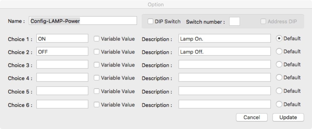
Define fixture options such as DMX Lamp Off, Pan/Tilt Invert and ‘Studio Mode’, for example. Additionally specify whether the option is set via a menu, or a dip switch. Buttons allow the adding of new options and editing or deleting existing options. Conformation will be requested before an option can be deleted.

To add a new option, enter a name for the option (typically the menu path as it appears on the fixture), and then the option choices, along with a description for each choice. Use the associated radio buttons to select the default choice for that option.
By default it is assumed the options are set via a menu system. If the option is set by a dip switch, check the ‘DIP Switch’ box. Enter the corresponding switch number. If the switch is part of the DMX addressing block of switches, check the ‘Address DIP’ box. For example. Under the Control Tab, 12 DIP switches could be defined, of which only the first 9 may be address switches, with switches 10, 11 and 12 being option switches. This information is used in Rig Data, under the Menu/DIP toolbar button.

Gobos Tab

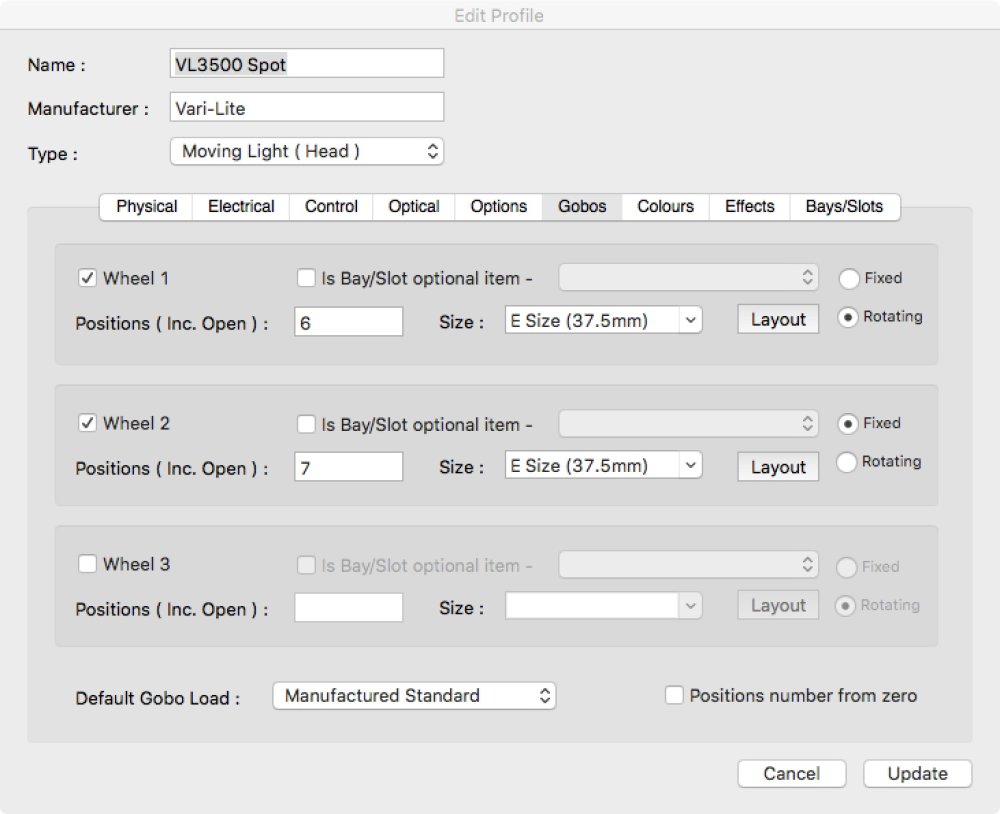
Define the fixture’s gobo wheels. Up to three gobo wheels may be defined per fixture. Enter the number of positions, including open, in the wheel, and select the gobo size from the drop-down list. New custom sizes, may also be entered directly in to this box. Define whether the wheel is fixed or rotating using the radio buttons. If the wheel in question is an interchangeable option that fits in to a bay or slot within the fixture, then check the relevant box and select the module name from the drop-down list. The bay or slot modules must first be defined under the ‘Bays/Slots’ tab. The Layout button defines the wheel graphic which will be used when viewing Wheel Loads.
Wheel Layout

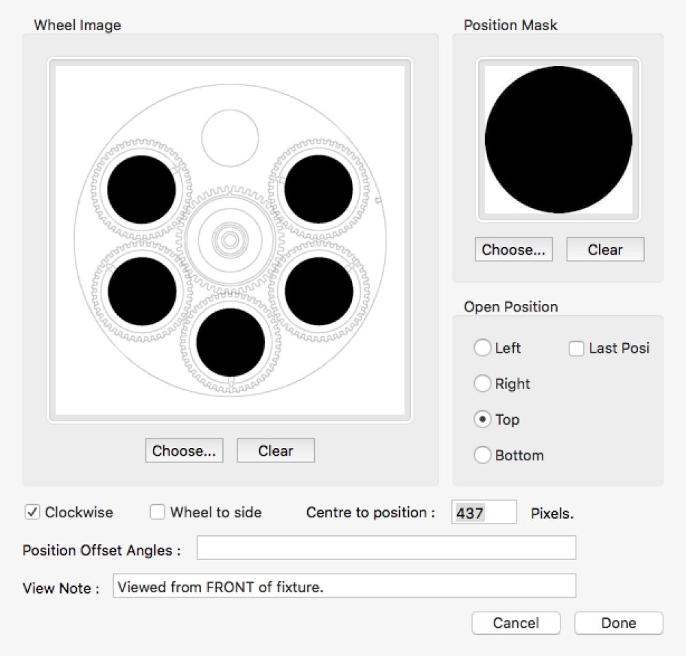
Wheel Layout graphics consist of two parts. A graphic of the wheel itself (wheel image), and a mask the same size as the positions in the wheel. Both graphics should be in jpeg format.
The wheel image should be 1500×1500 pixels, with the wheel itself being approximately 1300 pixels in diameter. This allows room around the perimeter of the wheel for the position numbers to be shown, if selected to do so in the Wheel Loads view. Ensure the centre of the wheel image is at 750,750 pixels.
The position mask should be a black circle (or other shape if the gobo position is not circular) and the same size as the positions in the main wheel image.
Specify the number of pixels between the centre of the gobo wheel and the optical centre of the gobo positions.
‘Open Position’ – Specify, using the radio buttons where about on the wheel the open position is.
‘Clockwise’ checkbox – Check this box if the positions are numbered clockwise from the open position. Leave un-checked if they are number counter clockwise.
‘Wheel to side’ checkbox – Check this box if the wheel sits to the side of the optical path in the fixture. Leave un-checked if the wheel sits above or below the optical path. This ensures that gobos that have a specific orientation will be displayed correctly in Wheel Load view.
‘Position Offset Angles’ – By default, Moving Light Assistant assumes the gobo positions are equally spaced around the wheel, and this field may be left empty. Occasionally, wheels may be encountered where this is not true, in which case, specific angles between the positions may be specified as a series of comma separated values, starting at the open position, and working up through the position numbers.

‘View Notes’ – A text field for entering any relevant notes. Most commonly used for describing which side of the wheel the layout is representing. For example: ‘Viewed from front of fixture’.
The default gobo load drop-down list defines the default gobo load for each wheel. The options are ‘None’ (Empty Wheel by default), ‘Manufactured Standard’ or ‘Edit’. If other default loads have been defined, they will also be available in this list.
Select Edit to define a new default gobo load, or edit an existing one.

To define a new default gobo load, click New, or to define a new default gobo load based upon an existing load, click on Duplicate. You will be asked for a name for the new or duplicate load.

Enter a name for the new load, and define which wheel the load applies to. The number of positions already defined for that wheel will be displayed as a list. Enter the gobo catalogue name, reference number, and title for each position, remembering not to populate the ‘open’ position. The name, number and title should correspond to the ‘Gobo Library’ nomenclature if the default wheel loads are to display correctly in Wheel Loads.
Colours Tab

Define the fixture’s colour wheels. Up to three colour wheels may be defined per fixture. This is functionally the same as the ‘Gobo’ tab. Scrollers may also be defined in this window. To accommodate scroller gel strings, Moving Light Assistant allows up to 32 positions in the ‘wheel’. Check the ‘Is a scroller’ check box.
Effects Tab

Define the fixture’s effects wheels. Two effects wheels and one animation wheel may be defined per fixture. This is functionally the same as the Gobo Tab.
Bays/Slots Tab

If a fixture includes ‘bays’ or ‘slots’ which allow modules to be added and removed, define the bays, and available module options here. Up to two bays/slots may be defined, with six available modules in each. Module descriptions may be selected from the drop-down list, or new modules described by typing directly in to the box. It is also possible to define an internal media frame, and the media it is fitted with. Usually, but not exclusively, a frost. The bays/slots functionality is very much geared around the ETC Revolution fixture.


