
Overview
This article covers the required setup when programming the User Interface to interact with the ClearOne Converge Pro 2 hardware. This article covers
- What device to import
- Aliasing of Channel Names
- Using the Dialer
- Gateway Setup
Process
- Launch Builder
- Create User Interface
- Import Devices
The image below shows the Add Devices pop-up window, search Manufacturer = Clearone and Model = pro 2
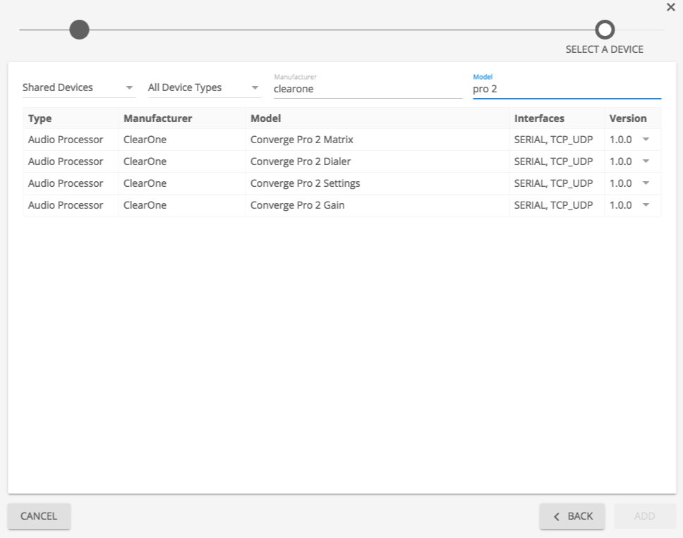
Each portion of the Clearone controls is broken down into separate devices. This keeps the categories and capability list shorter and easier for the programmer to locate the necessary commands.
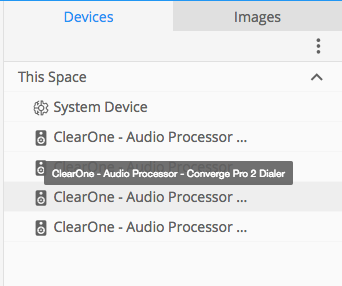
Add each of the the devices that will be used within the space
Aliases
Each of the controlled end points in the Clearone software need to be Aliased within the Kramer Control builder. These names are used within the Command Strings necessary to control the hardware.
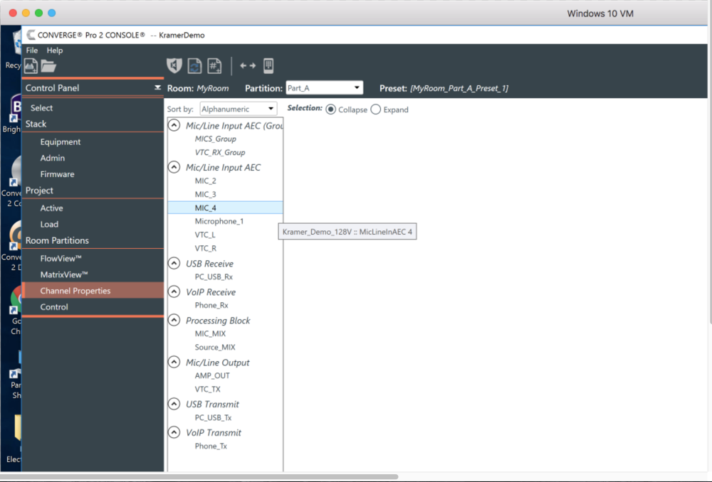
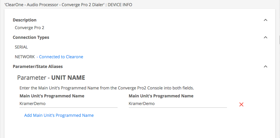
The image below shows the End Point Names found within the Clearone software. This is a screen capture of the ClearOne software, within the very top bar we see the name KramerDemo, this is the unit name and will also be necessary for the unit name. In the center section we see Mic/Line Input AEC and names below. The names below are used within the Aliases found below.
The image below shows the aliased names within the Kramer Control builder
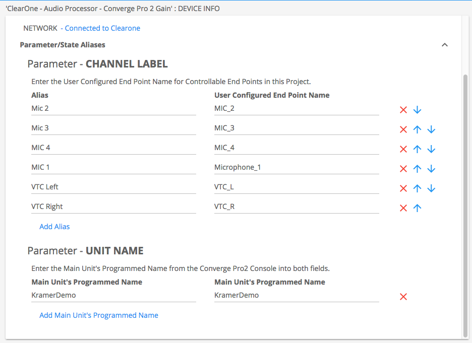
You will also notice the second alias at the bottom of the image showing the Unit name. This is also required for control, and the programmed name MUST exactly match for case when creating the Alias
Adding commands to buttons
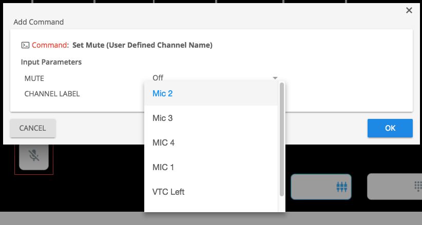
Within the Converge Pro 2 Gain device, we have commands with the (User Defined Channel Name) at the end of the command name. These commands will reference the Aliases created within the prior step
Using the Clearone Dialer
Within the link above, you will find a step-by-step setup for a generic dialer. The ClearOne follows the same steps and we will show those below
Dialer Aliasing
The ClearOne dialer device only requires the Unit Name Alias. This Alias will need to be created before any commands will work
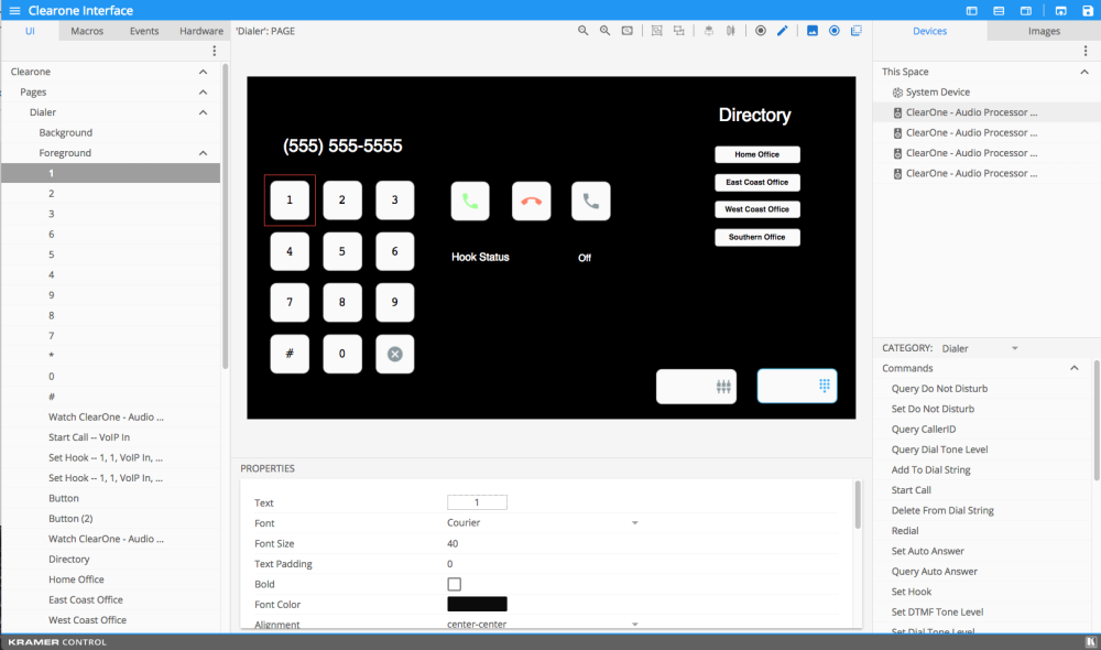
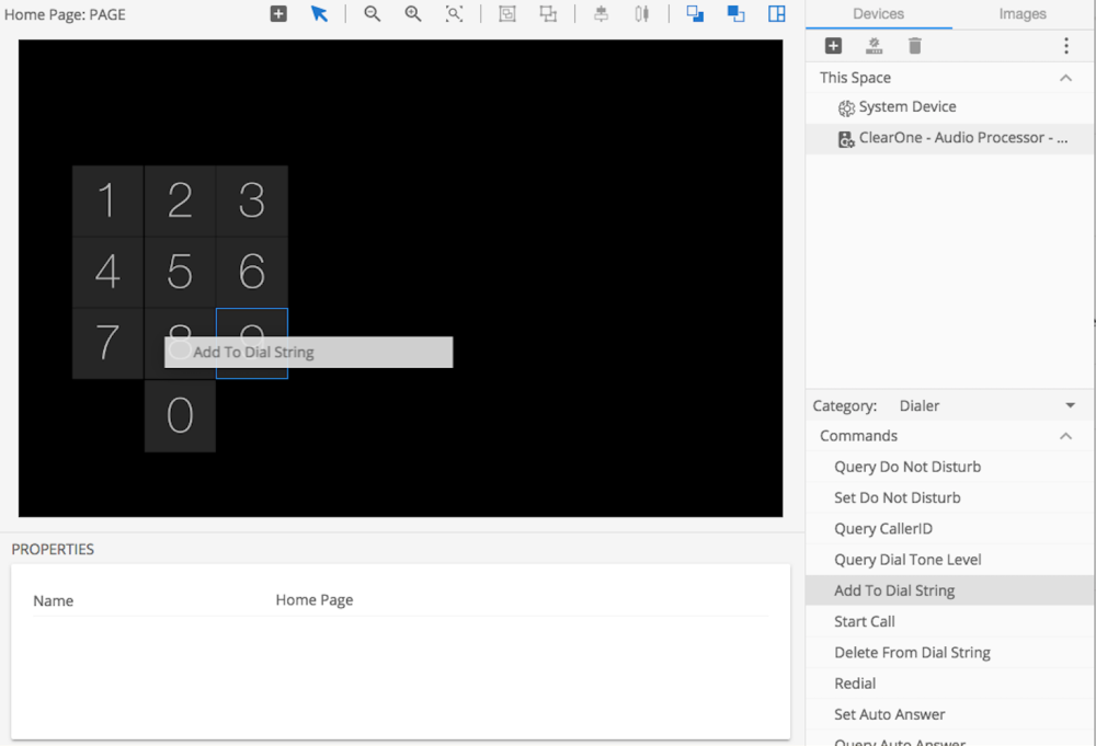
Create a dial pad within your User Interface using images and text to show the numerical value of the widgets
Use the Add to Dial String command to the numerical widgets added in the prior step
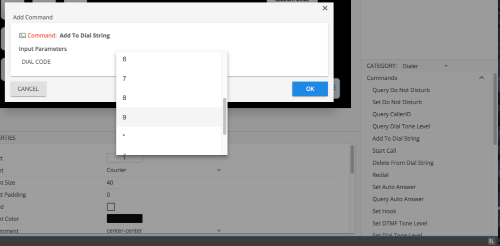
Repeat the above steps until all numerical widgets have the Add To Dial String command added.
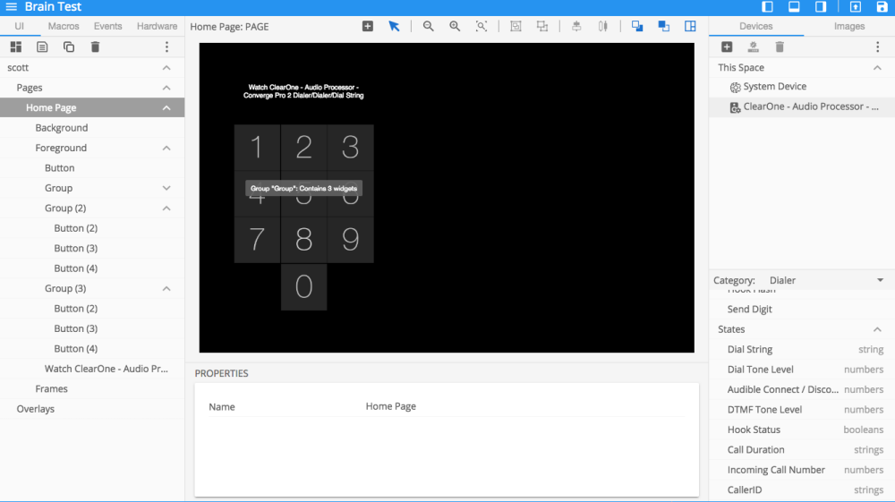
Add the Dial String State to the UI and resize appropriately to match your setup.
- This Dial String will show the digits that have been added by pressing the number pad buttons
Add Button that will be used to Start Call or Dial Call and add the Start Call command to this button

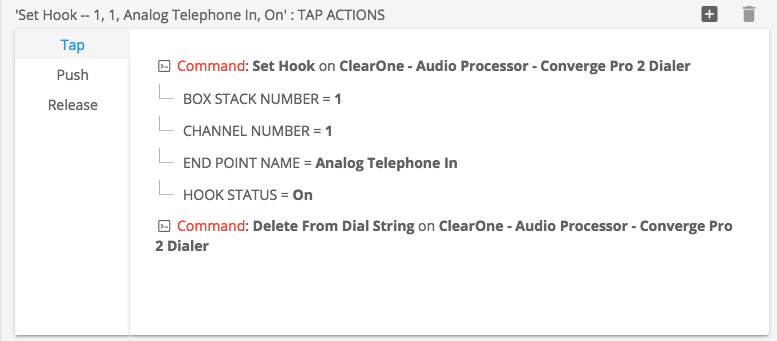
Add Button that will be used to End Call and add the Set Hook On command to this button. You will also want to include the Delete from Dial String command to clear the Dial String State from the Brain
- The ClearOne protocol uses Hook state to track calls. When the Hook is set to On, that means there is no current calls on-going
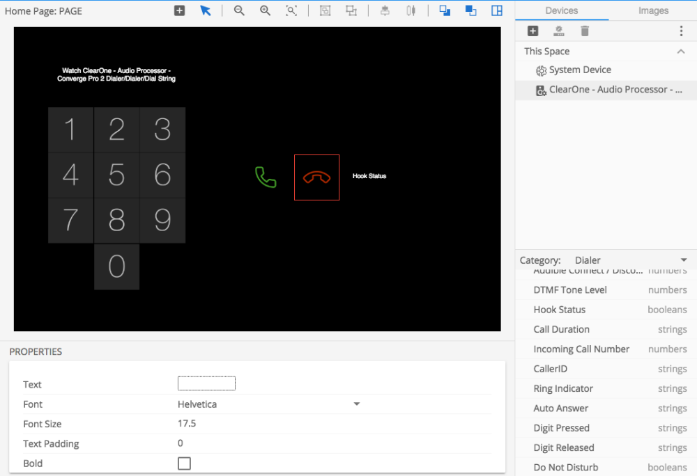
If you want to add the Hook State to the UI, you can drag the Hook Status state to the UI and resize appropriately
- In this example, I have created a blank button and added the Hook Status to track the Analog Telephone In state
Hardware/Gateway Setup
Add Network Gateway
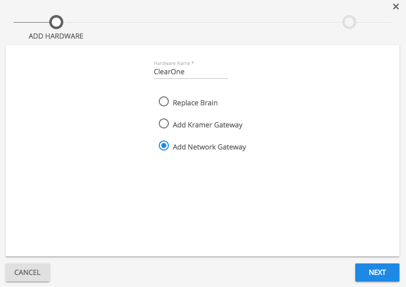
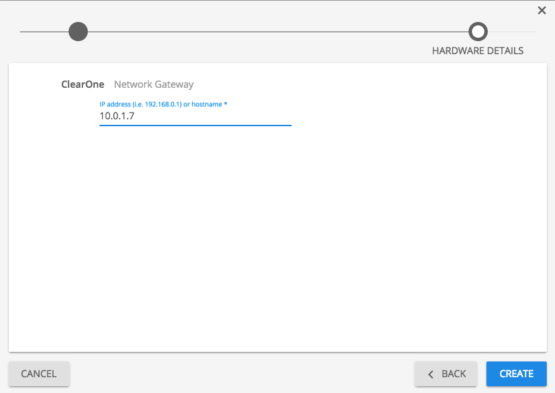
Enter IP address of ClearOne device on the network
Drag and Drop ClearOne devices to center pane of the new network Gateway
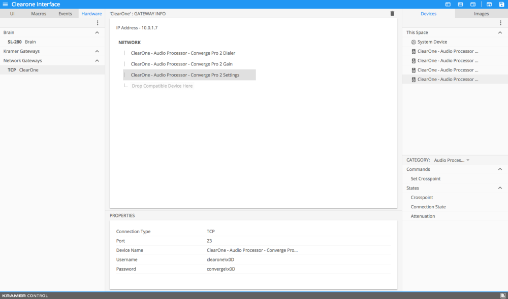
Once the gateway is setup, Publish your setup
Results
The image below shows the User Interface that was previously created. The image specifically shows the dialer with the Dial String event showing above the number pad we created

Post your comment on this topic.