
This function allows you to project selected elements parallel to a reference plane onto a target plane.
This is especially useful where planes meet at angles other than 90° and their final position is not known, such as a sloped waterfall panel that meets a floor at an angle.
How to Use:
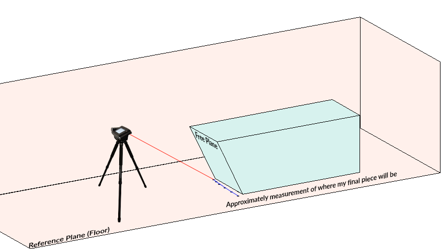
Example: scribe on the bottom of a sloped waterfall panel
In this example, the scribe where the panel meets the floor should remain at the same elevation along the floor, even when the panel’s free plane is offset to its final position.
- Measure your free plane as usual, with Distance Point to Plane point for editing later.
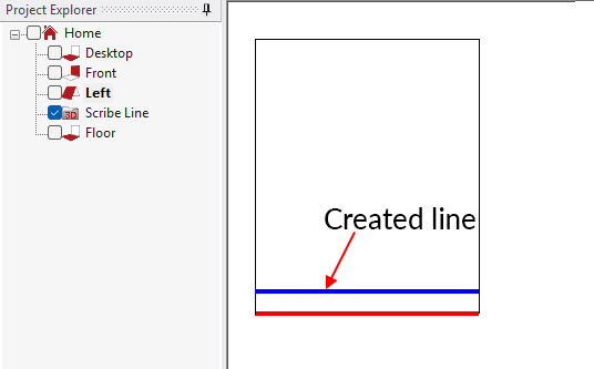
- For the scribe line to be projected, create a separate 3D folder, and then measure the scribe approximately where your final piece scribes to the floor.
![]()
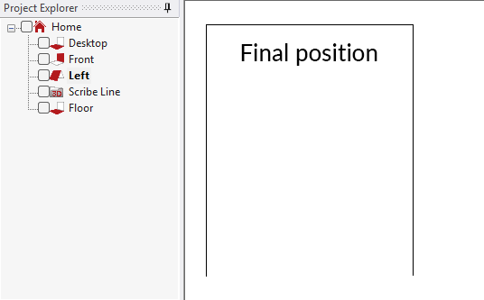
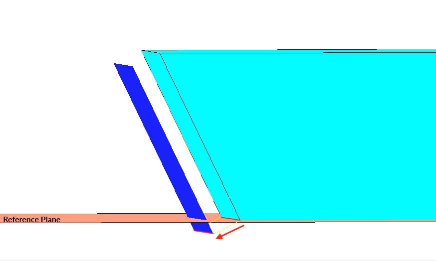
- Edit your plane to its final position. The scribe line will overlay in the incorrect position when visible.
![]()
- Activate the function from the ‘Change’ ribbon.
![]()
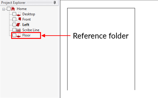
- Select the reference folder parallel to which plane the elements will be projected from the ‘project explorer’. (For example, this folder would be the floor where your waterfall will end)
![]()
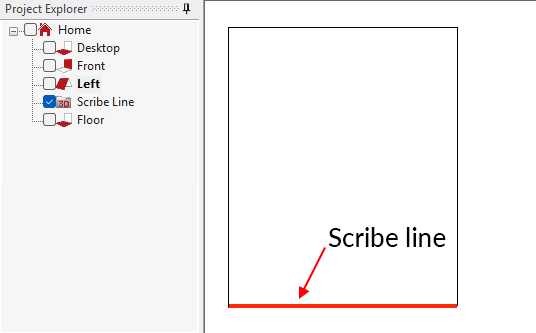
- Turn on visibility to the 3D folder with the scribe element to be projected, and then select the element to be projected and click confirm.
![]()
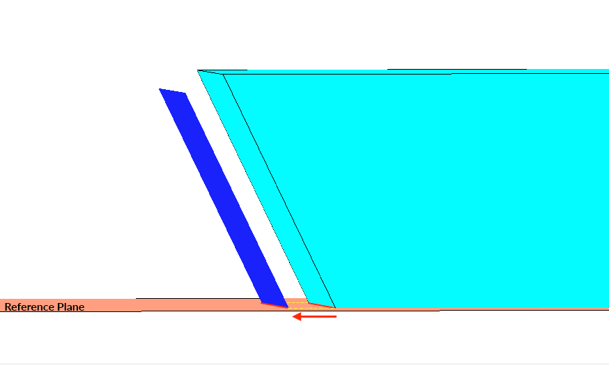
- The function will create a projected copy of the selected elements parallel to the target folder.
![]()

Differences between Project Elements Parallel to Plane and 2D projection
When an element is a 2D projected, the element is moved perpendicular to the plane. In the same way, if you only offset the original plane, it would be moved perfectly perpendicular following the plane’s direction.
But if you use Project Elements Parallel to Plane, this would project the elements based in the direction of the reference plane.
Post your comment on this topic.