
The remaining modules are added in similar fashion. We go to the Device view for each of the modules to see the starting byte addresses for their respective input and output data and use this when we create our tags for these modules.
| For the spur module, when we look at its Device view we see that its starting input and output byte offset is 128. From the chart in the UDT Assignment Example topic, we know that the spur module is in Reduced ZPA mode. | 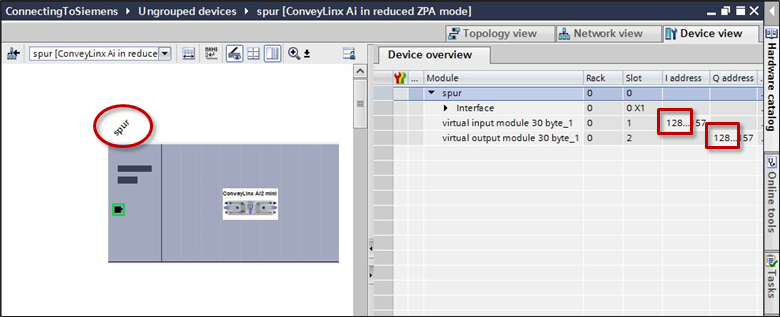 |
| For the reject module, when we look at its Device view we see that its starting input and output byte offset is 158. From the chart in the UDT Assignment Example topic, we know that the spur module is in Reduced PLC mode. | 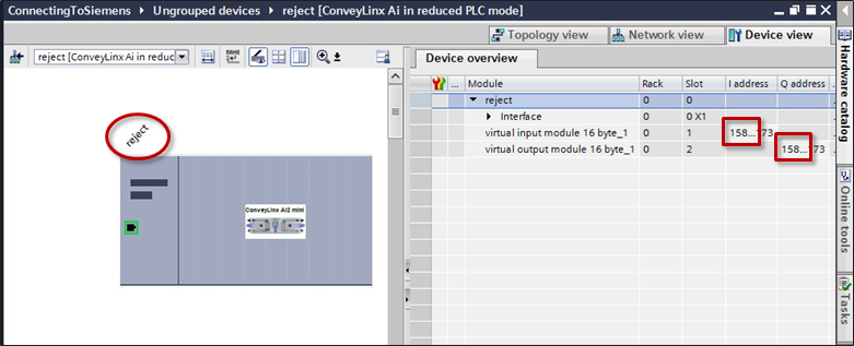 |
| For the reject module, when we look at its Device view we see that its starting input and output byte offset is 174. From the chart in the UDT Assignment Example topic, we know that the spur module is in Reduced PLC mode. | 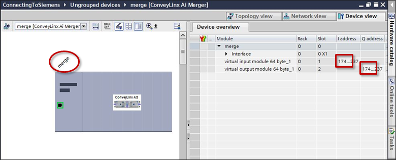 |
| With all starting byte offsets known and following the naming convention we used for the feeder and workstation modules, we can complete creating our tags mapped to UDTs | 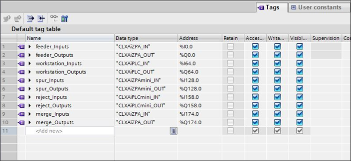 |