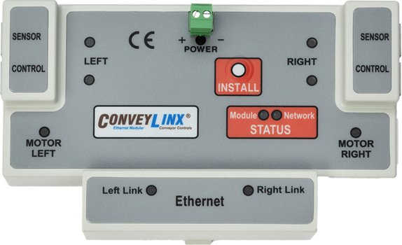
ConveyLinx-Ai/Ai2/Ai3 24V Family |
ConveyLinx ERSC ❌ |
ConveyLinx-Ai 24V ✅ |
ConveyLinx-Ai 48V ❌ |
![]() |
![]() |
![]() |
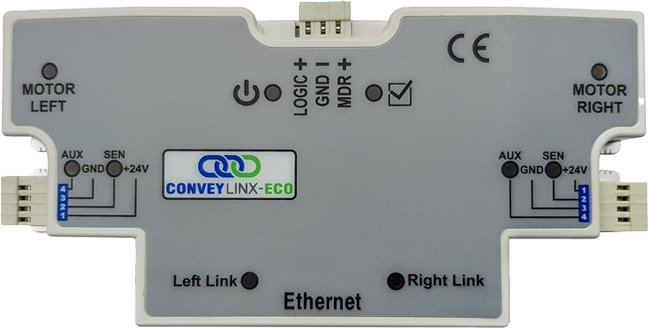
| ConveyLinx-ECO ❌ |
ZPA Mode ✅ |
PLC I/O Mode ✅ |
![]() |
![]() |
![]() |
![]()
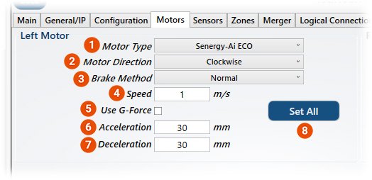
*Note that this image shows the Left Motor Settings. The same selections apply for the Right Motor Settings
| Item |
Function |
Description |
![]() |
Motor Type |
- Dropdown of Motor Types
- Each type is related to motor performance
- List shows only types available for the controller being viewed
|
![]() |
Motor Direction |
- Selects either Clockwise or Counterclokwise
- See Motor Rotation in Appendix for more information
|
![]() |
Brake Method |
- Dropdown of Holding Brake Methods
- List shows only types available for the controller being viewed
|
![]() |
Speed |
- Value input box to enter desired speed
- Motor speed value is in percent of maximum speed of motor/gearbox being controlled
- 100 is the maximum value
|
![]() |
Use G-Force |
- When checked, motor accel / decel is based upon constant G-force
- With this setting enabled the accel time and distance is variable
|
![]() |
Acceleration |
- Value input box to enter desired acceleration value
- When Use G-Force is unchecked, the value is distance in mm
- When Use G-Force is checked, the value is in m/sec²
|
![]() |
Deceleration |
- Value input box to enter desired deceleration value
- When Use G-Force is unchecked, the value is distance in mm
- When Use G-Force is checked, the value is in m/sec²
|
![]() |
Set All |
- Click button to apply these settings to a range of modules.
- Pop-up dialogue box will provide list of other controllers to apply the settings to
- Settings will only apply to the side of the controller (Left or Right) for which you are changing settings
|
Online Motor Page of the ConveyLinx-Ai/Ai2/Ai3 24V module
![]()
| Item |
Function |
Description |
![]() |
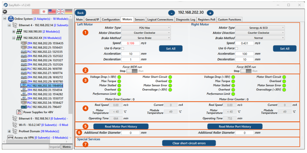
Motor Settings |
- Includes Motor Type drop down, 7% Overspeed checkbox, Motor Direction drop down, Brake Method drop down, Speed textbox, Use G-Force checkbox, Acceleration textbox, Deceleration textbox, and the Set All button.
- The Set All button provides the ability to make a setting apply to multiple motors in one or more subnets
- This section of the image is the only portion that is available when online AND offline
|
![]() |
Force MDR Run |
- When toggled the motor will run, great for trouble shooting
|
![]() |
Motor Errors & States |
- Potential motor errors include Voltage Drop (<18V), Motor Short-Circuit, Max Torque, Overload, Motor Stalled, Motor Sensor Error, Overheat, Overvoltage, Performance Limit
- At the end of this section shows the number of Motor Errors that have been counted by the module
|
![]() |
Motor Readings |
- Includes Real Speed, Current, Motor Temperature, Module Temperature, and Operating Time
- Each represented data point will change as the reading changes when online, these values are not represented when offline
|
![]() |
Read Motor Port History |
- Shows the information for motors that have been connected to the left motor port for the left, and right motor port for the right.
- Please note that this may display testing / factory data on new modules, so seeing Japan or Europe on this log is normal.
|
![]() |
Additional Roller Diameter |
- If the Roller has a greater diameter due to the circumstance of your application (coatings, etc), this should be entered and accounted for so that the system can accurately track the roller
- Diameter must be in millimeters
|
![]() |
Special Services |
- Clear short-circuit errors on both connected motors by clicking this button
|
*More information on the motors themselves can be found in their respective manuals on our website


Post your comment on this topic.