Brake Method |
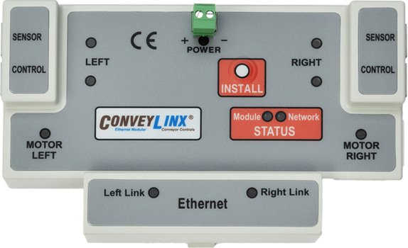
ConveyLinx ERSC ✅ |
ConveyLinx-Ai 24V ✅ |
ConveyLinx-Ai 48V ✅ |
![]() |
![]() |
![]() |
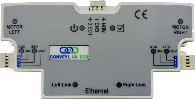
| ConveyLinx-ECO ✅ |
ZPA Mode ✅ |
PLC I/O Mode ✅ |
![]() |
![]() |
![]() |
The available Brake Method selections vary depending upon the controller family you are using. Here are the selection descriptions based upon controller family:
ConveyLinx-Ai2 / Ai3 Both 24V and 48V
| Method |
Description |
| Normal |
Once the controls have decelerated the rotor to a stop, the motor coil are internally connected. The permanent magnet forces in the rotor and the mechanical inertia of the gearbox holds the rotor in place. This is the MDR industry standard holding brake method and is often termed short circuit or shunt. Normal is the default factory setting for all module zones from the Auto-Configuration Procedure |
| Free |
Once the controls have decelerated the rotor to a stop, the motor coils are internally disconnected and only the mechanical gearbox inertia holds the rotor in place |
| Servo Brake |
When the controls have decelerated the rotor to a stop, the processor notes the Hall Effect sensor status. If the Hall Effect sensor status changes indicating a change in position of the rotor, the controls will inject current into the motor coils in the proper sequence to move the rotor back to its original stop position |
| Continuous Torque |
When the controls have decelerated the rotor to a stop, the processor monitors the Hall Effect sensor status. If the Hall Effect sensor status changes indicating a change in position of the rotor, the controls will inject current into the motor coils to generate torque in order to try and stop the rotor. Unlike the Servo Brake function, the controls do not try and return the rotor to its original stop position |
!Servo Brake function utilizes motor power and depending on the torque demanded by the motor to hold the load the potential for heat build-up exists
*Continuous Torque Brake method requires EasyRoll version 4.21 or later
ConveyLinx-ERSC
| Method |
Description |
| Normal |
Once the controls have decelerated the rotor to a stop, the motor coil are internally connected. The permanent magnet forces in the rotor and the mechanical inertia of the gearbox holds the rotor in place. This is the MDR industry standard holding brake method and is often termed short circuit or shunt. Normal is the default factory setting for all module zones from the Auto-Configuration Procedure |
| Free |
Once the controls have decelerated the rotor to a stop, the motor coils are internally disconnected and only the mechanical gearbox inertia holds the rotor in place |
| Servo Brake 1 |
When the controls have decelerated the rotor to a stop, the processor notes the Hall Effect sensor status. If the Hall Effect sensor status changes indicating a change in position of the rotor, the controls will inject current into 2 of the 3 motor coils in the proper sequence to move the rotor back to its original stop position |
| Servo Brake 2 |
When the controls have decelerated the rotor to a stop, the processor notes the Hall Effect sensor status. If the Hall Effect sensor status changes indicating a change in position of the rotor, the controls will inject current into all 3 of the motor coils in the proper sequence to move the rotor back to its original stop position |
*Please note that if you change the Brake Method and this module goes through another Auto Configuration procedure, the Brake Method setting will not reset back to default. It will remain unchanged at the last selected setting.
!Servo Brake 1 and 2 are functionally equivalent. Servo Brake 2 utilizes more power and provides more holding torque. Consequently, because Servo 2 uses more current, the potential for heat build-up is present depending on your application. If Servo Brake 1 provides enough holding torque for the application, it is recommended using it in lieu of Servo Brake 2. Servo Brake 2 should only be used when Servo Brake 1 does not provide enough holding torque for the application
ConveyLinx-ECO
| Method |
Description |
| Normal |
Once the controls have decelerated the rotor to a stop, the motor coil are internally connected. The permanent magnet forces in the rotor and the mechanical inertia of the gearbox holds the rotor in place. This is the MDR industry standard holding brake method and is often termed short circuit or shunt. Normal is the defauilt factory setting for all module zones from the Auto-Configuration Procedure. |
| Free |
Once the controls have decelerating the rotor to a stop, the motor coils are internally disconnected and only the mechanical gearbox inertia holds the rotor in place. |
| Servo Brake |
When the controls have decelerated the rotor to a stop, the processor notes the Hall Effect sensor status. If the Hall Effect sensor status changes indicating a change in position of the rotor, the controls will inject current into the motor coils in the proper sequence to move the rotor back to its original stop position. |
| Continuous Torque |
When the controls have decelerated the rotor to a stop, the processor monitors the Hall Effect sensor status. If the Hall Effect sensor status changes indicating a change in position of the rotor, the controls will inject current into the motor coils to generate torque in order to try to stop the rotor. Unlike the Servo Brake function, the controls do not try to return the rotor to its original stop position. |


Post your comment on this topic.