
Once the measurements have been taken, contoured maps are produced to allow the MWD contractor to interpolate suitable magnetic field values for use on his well.
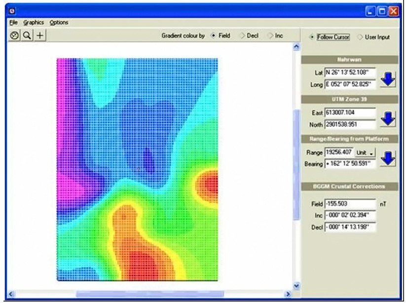
The IFR survey results are usually provided as digital data files which can be viewed with the supplied computer program. This allows the contractor to view the data and determine magnetic field values at any point within the oilfield.
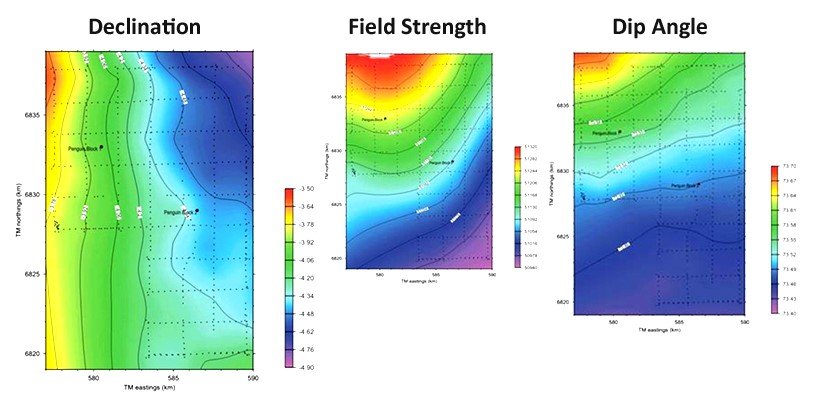
Two versions of the field maps are supplied. The first shows the absolute values of the total field, declination and dip angles, observed at the time of the IFR survey. The second set of maps shows how these values differed from the predictions of the BGGM model, due to the magnetic effects of Earth’s crust in the oilfield. It is these crustal corrections which are used by MWD contractors.
The crustal corrections vary only on geological timescales and therefore can be considered to be fixed over the lifetime of the field. The BGGM model does a very good job of tracking the time variation in the overall magnetic field. By combining the BGGM model and the IFR crustal corrections, the MWD contractor obtains the best estimate of the magnetic field at the rig.
First, we use the BGGM model to get an estimate of the total field, dip and declination.
Then the IFR correction values for the background magnetic field are applied by adding the BGGM values and the corrections. i.e.
| Total Field | Tf = TfBGGM + TfCrustal Correction |
| Declination | Dec = DecBGGM + DecCrustal Correction |
| Dip Angle | Dip = DipBGGM + DipCrustal Correction |
In most cases, this just involves selecting the location of the rig and choosing a single set of crustal corrections. In some cases, when the magnetic gradients are strong, the MWD contractor may chose a different declination for each hole section along the wellbore. If the declination or dip value varied by more than 0.1 degrees, or the field strength varied by more than 50nT along the wellbore, it would be recommended to derive values for each hole section.
Once IFR has been applied to an MWD survey, the contractor can change the error model applied to the survey to determine the uncertainty on its position. The Industry Steering Committee for Wellbore Survey Accuracy (ISCWSA) maintain industry standard error models for MWD that allow software to determine the positional uncertainty of the wellpath.
Normal MWD for example would have a declination error component of 0.36 degrees at 1 standard deviation but with IFR this is reduced to 0.15 degrees.
The effect of all this is to significantly reduce the uncertainty of the well position with all the benefits of the improved accuracy for collision risk, target sizing, close proximity drilling, log positional accuracy, relief well planning and so on.

Post your comment on this topic.