
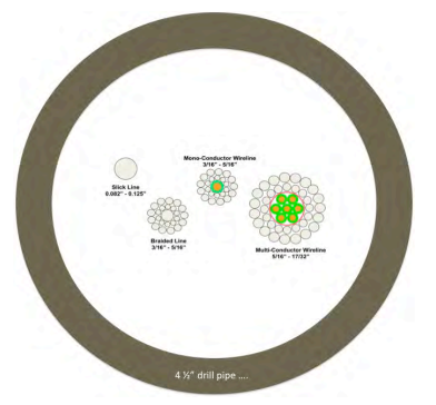
Drill pipe and wireline have fundamental differences, and are subject to totally different measurement influences. It is clear from Fig. 70 that the measurement systems used and the applicable corrections are different and will lead to different results unless there is meticulous application of calibration methodologies and corrections. It is also clear from the diagram that the correction coefficients between various sizes of pipe, tubing, coiled tubing, eline, braided line and slickline will vary considerably. Hence the medium used to create the measurement must be understood and characterized before a Raw Depth can be developed through to a True Along Hole Depth.
A major different in how Driller’s Depth and wireline depth are defined is inherent in the role that the measurement process plays. Drill’s Depth (and hence LWD/MWD depths) is defined while drilling, going down
the hole, with the drill pipe in a combination of tension and compression, typically rotating and sliding. Wireline depth is defined while measuring the hole, going up with increasing tension alone the line. Drill pipe MWD measurements are made in-situ, while drilling.
During the drilling process the drill pipe is subject to various changes in associated stresses, such as changes to WOB, sliding and rotating, pressure fluctuations in the pipe, changes in mud density inside and outside of the pipe, torque of the drill pipe, temperature variances due to mud versus formation temperature, etc. This means that when Drillers’ Depth (and hence LWD/MWD depth) is defined the associated corrections are highly complex and variable, and most importantly, not repeatable. This is a major difference with wireline where the tension regime is repeatable as are the depth determination conditions.
The below Figure Comparison of depth measurement mediums (not to scale)
Thermal expansion
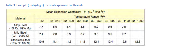
Thermal expansion affects the measured depth by adding depth to the measured value with increasing temperature. Knowledge of the thermal expansion coefficients is required to provide a credible thermal expansion correction.
What is important to realize is that the temperature is a gradient along the well, and the thermal expansion should be calculated as of the calibration temperature of the pipe or wireline. For this reason, the calibration temperature should be recorded as part of the pipe length or cable length calibration record.
The relationship for the thermal expansion correction is:
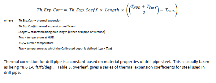
Being simply solid steel, slick line has a similar thermal expansion coefficient to drill pipe. This means that drill pipe and slick line undergo the same expansion in the same well.
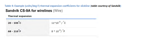
E-line (typ. larger 7-conductor) have different thermal expansion coefficients to that of drill pipe and steel because of the internal architecture and materials used in the core. Generally, as the wireline diameter increases the thermal coefficient decreases and is even negative, as the line length is effectively shortened with increasing temperature. But the thermal expansion coefficient is very dependent on the exact line being used, and care has to be taken in assuming any one coefficient as being valid for a different type of line of the same size. What is also important is that electric wireline can have different thermal expansion coefficients at different temperatures, further complicating the exact correction applicable. Table 5, below, gives a table of typical expansion coefficients for different sizes of wireline.
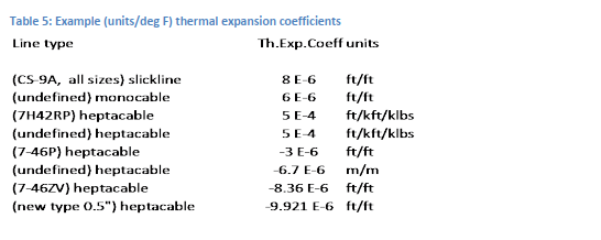
When determining the correction, it is important to be sure that the coefficient units correspond to the unitsbeing corrected for.
Surface versus down-hole tension
Tension measured at surface is often seen as a representation of the tension along the hole to TD. However, this is really only the case is a straight vertical well with negligible frictional influences. In this case, only, the tension at surface can be envisaged as being distributed evenly along the length of medium in the well to the BHA or tool string. In this case, changes in tension are representative of changes in the effective length of the pipe or line in the well and changes in the BHA or tool string friction.
In a real borehole, these changes in tension can be due to a multitude of other effects, including friction along the well bore, differential sticking, key seating, sloughing of formation, pipe or line weight supported by the borehole wall, hydraulic pressure changes, etc. In other words, the tension at surface is a complex composite of numerous factors.
However, specifically in the case of wireline, surface tension during POOH is repeatable at given speeds, and across specific well bore increments is also repeatable. This means that a logging tension measured at e.g. 1,000 m will repeat with the same value at the same speed.
The below Figure Example of wireline logged tension repeatability
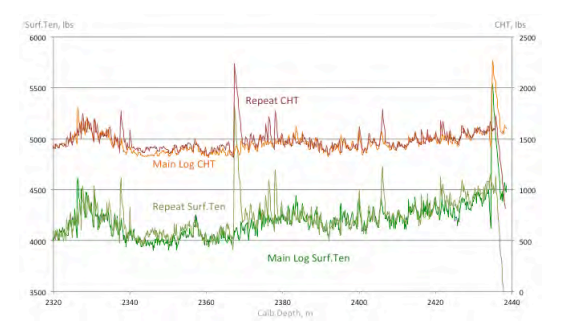
When measuring from surface, during POOH the tension in the wireline can be seen as incrementally decreasing between any two points such that any change in the tension can be corrected for according to the elastic correction coefficients valid between these points. This means that not only the tension but also the elastic stretch for a wireline is repeatable. This also means that corrections can be incrementally introduced between individual measurement points when using wireline.
For drill pipe this is not true, as the WOB and drilling parameters (mud pressure, density, flow rates, sliding/rotating, torque, etc.) change during the drilling process, such that the effective position of the BHA is not
the same during the drilling and subsequent ascents and then descents in the hole. As the LWD and MWD measurements are defined using drillers’ depths, it is clear that there is significant opportunity for inconsistency between the measurements made during first drilled descent and subsequent ascents and descents. For this reason it is also obvious that first drilled depths cannot be expected to correspond to wireline depths.
Tension and stretch regimes
A tension regime is a description of the changes in tension with depth that the wireline undergoes during descent and then the ascent. Under normal conditions, the tension regime during pull out of hole (POOH) at logging speeds is repeatable, creating the ability to determine incremental corrections between points that are repeatable and hence predictable.
A stretch regime is the elastic stretch associated with a given tension regime. As the tension regime is repeatable and the parameters for elastic stretch are known, the stretch regime is then also repeatable and predictable between points.
The below Figure Tension regime differences between two sequential logging runs (Y-axis = logged surface tension, CHT (lbs) and depth (ft), Xaxis = data sequence number)
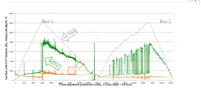
In the case of drilling, the tensions measured are not repeatable as, by definition, the hole is being drilled. This means the measurements made cannot be repeated, for verification purposes. Obviously, any subsequent descent and ascent of the drill pipe over a drilled interval will have a totally different tension characteristic.
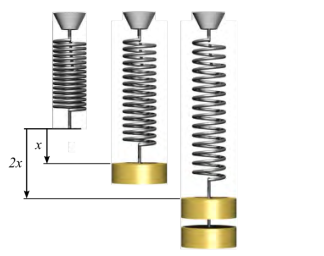
Elastic stretch equation
Hooke’s Law describes the elastic deformation of both pipe and wireline. From this an environmental correction for stretch (or compression in the case of drill pipe) can be made based on the elastic stretch equation insofar that the deformation is elastic and linear in character. In the case of well bores, the tension decreases going downhole because of there is increasing less line or pipe weight at any point through to the end of the line or pipe where the tool sting or BHA is.
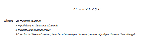
The equation used to determine drill pipe stretch is based on the calculated stretch constant based on the pipe
dimensions. Elastic stretch is then given4 as:
The equation used to provide wireline stretch correction in a borehole environment includes both surface and cablehead tension. This is then:
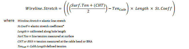
It is important to note the role of Calb.Ten, and when the length calibration is made this should be included (even if this is “zero”, such as is the case when strapping pipe on the pipe rack).
Stretch coefficient
The stretch coefficient is a major parameter in the stretch correction, and must be accurately known.
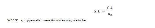
The stretch coefficient for drill pipe is based on the cross sectional area of the pipe and the material properties of the pipe. The general equation for stretch constant (S.C.) is:
Common drill pipe sizes are tabulated below. Note that it is stated (by BakerHughes): “It is a common misconception that the rate of stretch for oil field tubular material is also affected by the grade of steel (J-55, N- 80, etc.). This is not true. Higher grades of steel have greater elastic limits and can therefore be stretch further before reaching their elastic limits than can lower grades, but the rate of stretch is the same for all grades….”
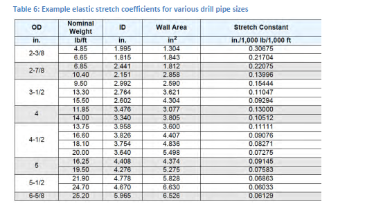
This is also true for slickline.
For braided and e-line this is not so, as the elastic stretch coefficient of the line is then also affected by the layand internal architecture of the wireline. The stretch coefficient also increases with higher tension. OEM values for stretch coefficient are often quoted, but these values relate to specified (near maximum pull) levels and refer to new lines after initial permanent deformation has been worked out of the line.
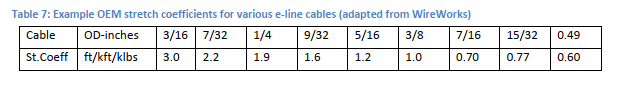
Actual stretch coefficients applicable to logging conditions are often lower than the OEM values. Stretch coefficient for wireline can be estimated from in-situ measurements made during HUD pick up and verified at
stick and pull events.
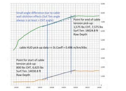
HUD stretch coefficient example for a 7-conductor cable
Wireline – initial permanent deformation
E-line is subject to initial permanent deformation (IPD) when new. IPD does not affect drill pipe of slickline. This phenomenon is caused by compression of the cable core (composed of copper conductor, insulation and packing material) and intrusion of the core insulation material into the bedding of the inner armour wire layer. There is also a settling of the armour wires into a lay pattern that allows minute, but critical, abrasion of the outer and inner armour wire layers. IPD continues through till when the stabilized core and armour wire spatial configuration is achieved. The progression of IPD over any length of cable depends on the temperature, the tension that the line is subject to and the number of pull cycles and the length of time of temperature and tension exposure. As a rule, the effect of IPD has manifested itself after 6 to 10 runs in the well. Correction for IPD has the effect of increasing measured depth, and is only applicable to POOH depths.
Drill pipe – specific corrections
Corrections for drill pipe depth measurement are varied, and complex. This comes because the pipe during drilling is at varying levels of tension, and compression, and the neutral point changes during the drilling. Further complication is the frictional losses along the drill pipe, and then torque that affects the amount of pipe in the hole. Drill pipe buckling will also affect the amount of pipe in the hole that is not reflected in the position of the bit (see Fig. 9). Ballooning of the pipe caused by mud pressure will shorten the pipe, but this varies with mud pressure and mud density. The WOB will also be affected by bit nozzle pressure.
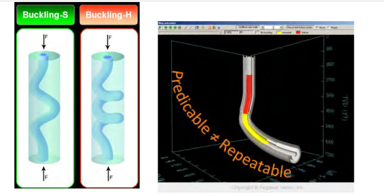
Sinusoidal and helical buckling of drill pipe causing measured Driller’s Depth to be greater than along hole length (images courtesy of Pegasus Vertex)
Dealing with Stick&Pull
Stick&Pull is usually a wireline depth data quality issue that manifests itself at short, but sudden, irregular buildups of tension at surface – often caused by the tool string being momentarily stuck and the suddenly releasing5. When these build-ups correspond to build-ups of CHT, then the cause is tool sticking. When caused by the tools string sticking, the build up of the line tension has the same (or almost the same) build-up as is experienced at TD.
Stick&Pull can also be caused by differential sticking and sometimes by key seating of the wireline cable. When the Stick&Pull is caused by long-hole cable sticking, the tension build-up angle is higher than that at TD.
Stick&Pull affects not only logged depths, but also in particular the responses of array instruments that useadjacent depth responses to calculate actual values. For this reason, the logged depth data should be made available for eventual recalculation of array data. One of the problems with this is the sudden tool movement atthe time of release can mean that a relatively large logging interval is passed by without the data being properly sampled through the interval.
In cased hole, Yo-Yo can occur as a function of simple harmonic oscillation of the line tension during POOH ascent of the tool string. This can usually be solved simply by changing the logging speed.
Stick&Pull does not affect the overall logged depth given that calibrated line is used. When measurehead-onlydepth is used, the measured depth data can be severely affected and the validity of the logged depth data is compromised.
When Surf.Ten, CHT and stretch coefficient data is available, Stick&Pull can be corrected real-time. The advantageof real-time correction is that array instruments are able to provide processing based on a corrected depth. This may require very fast processing, as much of the released depth movement occurs in a very short time. Stick&Pull can also be corrected post-operation, and be dealt with as an environmental correction. This should be done after all the other corrections have been applied6.
Other correction factors
There are numerous other influences, usually minor, that can affect along hole depth measurement by both drillpipe and wireline. These are not listed here, but most of these relate to the validity of the measurements of length, surface and downhole tension. The main corrections that affect wireline are thermal and elastic stretch correction. The main effects on drill pipe measurement are thermal and elastic stretch, and then a host of further drilling parameters as mentioned above. In any case, when corrections are made, these should be detailed in the depth data log, and should be so that they can always be reversed and re-calculated.
Correction determination process
The main correction process includes thermal and elastic stretch correction.
The important thing is that the correction is applied over logical intervals where the most obvious changes occur.These are usually identified by the tension regime and will correspond to changes in well geometry and majorchanges in drilled geology.
It is recommended that, per tension regime interval, the thermal correction is made and then the elastic stretch (followed by evt. other corrections) is applied over each individual interval sequentially.
Way-point depth navigation
Way point navigation is a wireline process sequence that allows the tension regime and hence stretch regime to be determined while running in hole, and then using this to correct for elastic stretch real-time during the ascent. The method relies on the repeatability of tension, as earlier described.
At points along the well bore while running in hole, and specifically at significant geological boundaries and know dog legs and other places where tension events are anticipated, the tool string is stopped and moved upwards at logging speed. The surface and cablehead tension values are noted.
It can be expected that these values will be repeated on the logging ascent, and yet each of the measured point values can be considered as incremental. That means that the tension and also stretch between any two points can be compared to arrive at a stretch contribution valid between these points. By adding these contributions up the total stretch applicable to the ascent can be mapped prior to pick up at HUD !
The below Figure Example of how to apply way-points in different types of wells
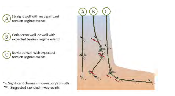
The way-points are selected as points where a tension check is made of surface and cablehead tension such that an approximation can be developed of the expected tension regime.
Measurement uncertainty determination
As has been elsewhere and earlier discussed, errors can be classified as systematic and random7.
Systematic errors in well depth measurement abound. They include errors related to well datum referencing, tool zero definition, incorrect measurement techniques or human error in procedure and reporting. They also include errors arising from operations performed outside the recommended performance envelope (over-pull, stick & pull, stuck line/tools, etc.). Problems of this nature are not dealt with in this paper even if, as individual incidents, they can have serious consequences. When unrecognized, systematic errors can be repeated and can become an ingrained error source, as there is no means of identifying them.
Driller’s Depth error has been described elsewhere.
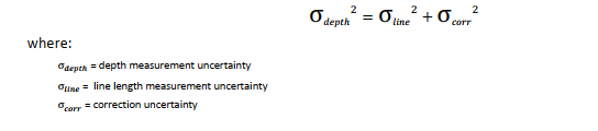
Wireline random – non-systematic – measurement uncertainty can be described as:
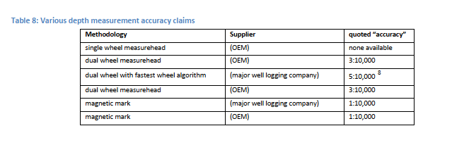
Calibration error is often described by logging companies as the measurement error, and a survey of various companies results in Table 8, overleaf:
The error model for the correction is then defined by the exact relationship used. This can vary, but is usually a function of the measurement error of the tension devices, the temperature measurement and the stretch and thermal expansion coefficient errors. In any case, per interval it is a single figure.
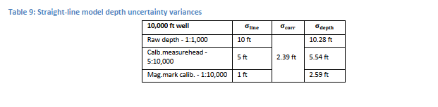
When a straight-line model is assumed for correction, this then leads to the following example of error (assuming
a correction model error of +/- 2.39 ft/10,000):
When the way-point model is used, the correction error is significantly affected, as the corrections per interval are smaller, albeit more numerous. The error is defined by:

But the total correction error is diminished (in this example, it will be assumed to be 1.46ft/10,000 ft). In this case, the uncertainty is then:
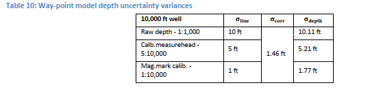
Tables 9 and 10 illustrate that uncertainties can be determined per logged depth data set. The differences between the uncertainties shown in tables 7 and 8 indicate that significant differences, and improvements, in measurement uncertainties can be achieved through the choice of the various available measurement methodologies.
Sources of error before measurement
There are a variety of potential error sources, the most important being calibration error and referencing error. Mundane – but critical: is a clear and unequivocal referencing of the surface reference points. This can be defined in a number of different ways, but it is absolutely necessary that whatever reference is used that it is applied consistently across all measurements made. When the rig moves off location, it is important that a sustainable referencing system is in place that allows the originally defined reference system to be applied.
Offshore, an important source of potential error is accounting for wave and tide error. This can be compensated for with wave compensation, but needs to be watched carefully.
Calibration error can, and does, occur. If the error is systematic, then given that the calibration parameters have been adequately noted, it may be possible to post-operationally recreate a calibrated length. If the effort is random, this is not possible.
Sources of operational error
Operational error is usually down to process error and this is invariably related to engineering and operational training and management. A critical element of pre-job preparation is assurance that the right skills are in place to provide the correct process and being able to deal with variances as they occur.
Mechanical error can also occur (measurehead error or failure, tension load cell failure, etc.), but the depth data provider should have in place a back-up system to allow the error to be identified and in any case allow a safe recovery to surface.
Meeting accuracy expectations
Table 1 proposes a series of accuracy requirements that can be considered as being applicable to the various tasks listed. It is not to say that this table is what it should be, but it does illustrate that different accuracy expectations are applicable to different stages of exploration, well construction, production and asset management. What is also important to recognize is that at the well site, during the depth data acquisition process, the depth data acquisition requirements may not be cognizant to the well site operations. For this reason it is of critical importance that these requirements are considered as part of the data requirements statement, and that the QA and QC functions are tuned to this.
Once the requirements are stated, it is up to the data provider to put in place the calibration, verification and correction processes that facilitate the required accuracy to be provided.
QA & QC check points
QA and QC have to be designed to assure that the data to the accuracy requirements are met, and verify that the processes and procedures followed are consistent and in accordance with the stated procedures of the depth data supplier. Given that this is the case, and given that the equipment and personnel involved in the depth data acquisition are able to perform the tasks, then the consistency, and accuracy, of the depth data provided will result in a manageable error margin.
Post your comment on this topic.