
Calibration is the determination of the instrument response relationship to the calibration standards applicable to the measurement
In the case of drill pipe, there is no real calibration other than the measurement of the pipe length, usually determined on the pipe racks. This is often done by hand using a steel tape measure, but is also done using
laser, measuring from shoulder-joint to shoulder-joint along the pipe length.
The below Figure for Drill pipe strapping in defining drill pipe length
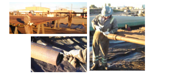
The below Figure for Drill pipe length measurement using laser (image courtesy of Digi-Tally)
The pipe tally is then used to define the pipe length in the hole, with interpolation of pipe length providing the continuous length measurement. When pipe length is environmentally corrected, various factors may be taken into account, and these should be detailed in the correction information. But invariably, these corrections are not
applied, and scant attention is paid to them.
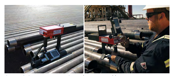
Some wireline companies rely on calibrated measureheads to provide line length, but unfortunately the measurement provided is then not corrected for existing line stretch, and the error can be significant. Other
companies use calibrated line length defined by magnetic marks with gives a far more robust line length measurement that can be verified through observation of the actual magnetic mark tally.
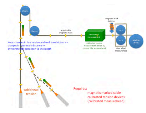
The below Figure, overleaf, illustrates the role of magnetic marks used when pulling out of hole. It can be seen that under varying tension conditions the magnetic marks define the length of cable between the surface and the tool string, and that this can then be corrected for stretch according to the surface and downhole cable head tension. It is important to note that without a credible calibration process the application of corrections is questionable.
Verification
Measurement verification of depth can be provided for Drillers’ Depth by logging the out-coming pipe depth, and for wireline logging the magnetic mark positions. Note that when logging wireline using a
measurehead only (i.e. without marks) there is no realistic measurement verification.
The objective of the verification process is to quantify the compliance of the measurement to the calibration process. This is shown by the conformance of the measurement to a known standard as well as stability of the measurements provided.
In the case of depth, this is difficult as a number of issues are not well defined. This includes the robustness and relevance of the calibration standards as applied to the depth measurement, the influence of environmental and measurement conditions on the measurements made, and the availability of a credible verification process and standard.
For drill pipe, the measurement made is based on the measured length of the drill pipe. Usually the temperature of the measurement process is not recorded, so that the relevance of temperature correction is at doubt. Also, the calibration process itself, including both systematic and well as random error induced by the rack-based pipe length measurement, is often not well defined.
Role of corrections
Corrections are designed to adjust the measurements made back to calibration conditions so that the accuracy of the calibration can be adhered to. The correction process should take into account all effects that materially affect the validity of the measurement compared to the calibration conditions.
The most common corrections on drill pipe include hydraulic pressure ballooning, thermal expansion, torque and in-hole buckling, tension and compression of the pipe along the well bore, rotational and sliding pipe frictional forces, weight support due to contact with the borehole wall, mud-weight buoyancy, mud movement frictional effects, pressure support at the bit.
Wireline corrections for first primary open hole logging are typically limited to thermal expansion and elastic stretch. Corrections for cased hole services are usually related to compensation to line tension related to
pressure. Typically this involves pressure support through wellhead control (GIT and stuffing box effects on surface tension) and measurement inaccuracies through sheave angle when using lower sheave wheel tension.
Stick&Pull affects wireline measurements, and can affect both first primary as well as cased hole. It can be either corrected real-time or post operationally.
Post your comment on this topic.