
It is sometimes difficult, or even impossible, to verify a given error model through independent estimation of all individual error parameters from downhole data. The magnetic declination, the sag and the depth error terms are, as indicated in Table 1, examples of parameters that cannot be estimated directly. It is therefore necessary that a method for final error model validation be used in addition to individual error term validations. The framework for the co-ordinate difference test can be used for this purpose. However, some equations and the test limits are slightly different, as described below. Both survey types used will of course have to have error models assigned to them.
The main difference between the basic co-ordinate difference test and error model validation is that the former is based on single sided Chi-square tests of a single pair of overlapping surveys, while error model
validation is based on two sided tests of multiple sets of overlapping surveys of the same type originating from different wells.
To ensure that the random between survey behavior takes precedence over the systematic between survey station behavior, the number of overlapping survey stations used from each survey pair should be
significantly smaller than the number of survey pairs used, but not so small that the random between station behavior takes precedence. Four overlapping stations from each survey pair spread over the survey stations available for each run, and at least 10 survey pairs seems to be a good compromise. An example that illustrates how this method can be used as a partial validation of a non-downhole derived error model is given below.
Example 3. Overlapping survey data (same type) from 3 different wells are used here to illustrate how the coordinate difference test can be used to verify a given error model, which in this case is identical to the error model recommended by the service provider. Both co-ordinate differences from the same survey (inrun/out-run differences), and from two different surveys in the same well (in-run/in-run and in-run/out-run differences), are used. Four sets of co-ordinate differences (taken at 25%, 50% and 75% of TD, and at TD) were used in each case. They are shown in the following plot.
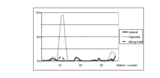
This provides a total of 36 test sets to combine. This is not enough for a final verification of the error model. Data from many more wells, including a substantial number of overlapping surveys made with different tools and different wireline units, would have been necessary to achieve a full verification. However, the data set should be sufficient to visualise the process of using the coordinate difference test for final error model validation.
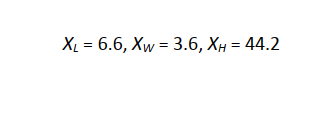
In accordance with the Chi-square test procedure3, the coordinate differences scaled by the error model variances of the survey systems used are summed over the number of survey stations and the number of
wells to give the following Chi-square test parameters. Along-hole, lateral and highside sums are denoted by the symbols XL, XW and XH respectively.
Upper and lower tolerance limits for all three cases are selected corresponding to the Chi-square test value for n degrees of freedom with 95% significance (Z0.95,n), and the Chi-square test value for n degrees of
freedom with 5% significance (Z0.05,n), where:

The along-hole and lateral sums are both smaller than the lower tolerance limit, while the highside sum is inside the tolerance limits. The results suggest that the recommended error model may be slightly
pessimistic. However, such a conclusion may not be valid since these results are based on too few surveys, and on data that may be correlated between surveys, and therefore overly optimistic.
Post your comment on this topic.