
All steels are magnetic to some degree but the mild steel, used in casing and lining is very magnetic. When steel pipe magnetises naturally in the earth’s magnetic field it tends to magnetise with the opposite polarity to the Earth Field. This means that pipe that has been stored together tends to have a change of polarity at every thread joint and a strong detectable magnetic field along its length. A magnetometer placed close to the steel, will measure the vector sum of the earth’s magnetic field and the steel magnetic field. A magnetic influence increases with the inverse square of the distance from the source. If we hold a magnetometer at half the distance, we see 4 times the field strength. As a result, the strength of the earth’s magnetic field can be considered to be relatively constant due the fact that the source, however strong, is so far away, but the influence of nearby steel will vary considerably depending on our proximity to it.
There are two broad types of magnetic ranging known as Passive and Active. Passive Magnetic Ranging uses a standard MWD sensor set, to detect changes in the background magnetic field. These changes are affected by the distance from the magnetic source as described above and the polarity of the influence which changes with every casing joint. It is possible then to observe the influence from several positions and ‘triangulate’ the location of the centerline of the other well from the results. This requires that the pole strength be sufficient to be ‘seen’ by the sensors and for practical reasons this unlikely beyond about 15m or 50ft.
Active Magnetic Ranging uses a power source downhole to inject current into the surrounding rock. When the current is passing through rock, the resistance is high but when the electrons find steel, they rush through the steel with very little resistance creating a very strong cylindrical magnetic field around the steel. This active magnetic induction can be ‘seen’ from up to 100ft away and is a popular alternative to passive ranging in relief well situations. However, although it provides more accuracy, the ranging tool requires a separate trip in hole and for a deep relief well, this is very time consuming. More recently an Active Ranging While Drilling (ARWD) tool has been developed which will provide an active ranging facility within an otherwise normal drilling assembly which is very useful for the closer range operations and avoids the need for tripping.
The magnetic field is detected using a set of three magnetometers but these are not arranged in the usual orthogonal geometry. They are arranged in a ring and set at 120 degrees to each other. The three readings will not exactly agree. The magnetometer closest to the source will show a stronger reading then the other two and the degradation in signal over the very short baseline provides an estimate of the distance.
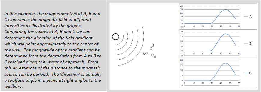
Clearly, this is very inaccurate when the field strength is weak and the degradation is very small from one signal to the other. This occurs when the target is a long way off and thus the uncertainty is very large. A first ranging shot is not worth taking unless you are within about 100ft of the target well.
Some Practical Considerations
1. A relief well can only be drilled from a safe location. This usually means that a relief well plan will estimate the prevailing wind direction and ‘smoke range’ and this determines the location of the relief
well rig. This will be a considerable distance from the target well so accurate surveying including surface positioning, is required in both for a successful relief well.
2. The kill point in a relief well cannot be any shallower than the point at which the hydrostatic head of kill mud exceeds the pressure in the target well. At this point the uncertainty may well be more than 100ft.
When planning the relief well, it is often required to design to a ‘location’ or ‘homing in’ point well shallow of the kill point. This point has to be shallow enough that the combined uncertainty of the relief
well and the target well does not exceed 100ft for active ranging and 50ft for passive ranging.
3. It is never allowed to approach the target well with a separation factor less than one before ranging. Once ranging is underway, the relative positioning uncertainty takes over but prior to the first ranging shot,
there must be no danger of colliding early with the target well or you may have two blowouts for the price of one.
4. When selecting the homing in point, it is important to remember that the ranging tool will only see the effects of one magnetic field no matter how many wells have contributed to it. It is vital then that at this point there is no danger of ranging to the wrong well. This then forces discipline in the planning stage especially on crowded platforms and pads where there has to be enough space for the relief well to reach the target without significant collision risk and for the target well response to be unambiguous. As a rough guide, all other wells should be at least three times the distance away that the target well is when taking the first ranging shot.
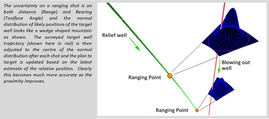
5. After each ranging shot, the survey on the target well is shifted to pass through the observed position. As you approach closer, this shift should reduce in size. If it increases in size, there is a danger that the
ranging is seeing more than one well and the procedure should build in more ranging checks to establish an unambiguous target. Another reason though may simply be a poor quality survey in the original well.
This is one of the main reasons why relief wells can be severely delayed as we ‘search’ for the trajectory of the other well. This is often a frustrating and expensive process often with considerable public interest
and the excuse that we saved money on surveying does not go down well in the press.
6. The combined uncertainty is a specialist calculation that looks at the sources of error affecting both the relief well position and the target well position. In the absence of anything else, if both wells are MWD, it
is safest to assume that both error ellipses are full size and geometrically add them together. However, in many cases, when a relief well is called for, the primary cost consideration is not surveying. There is
usually justification for multiple gyro runs to minimize the uncertainty on the relief well. (Gyros can be attached to the ranging tools for additional high quality in-runs and outruns with multiple overlaps). As a
result, in the calculation of combined uncertainty, the target well uncertainty dominates the error budget and the contribution of the relief well gyros is almost negligible in the sum of the squares of the errors
but it cannot be ignored completely.
7. When planning a relief well, if the homing in point is not the same as the kill point, it may be necessary to ‘track’ the target well until kill depth is achieved. This usually means that the relief well crew will want to
approach the homing in point with a similar inclination and direction as the target well to minimize steering to parallel in order to keep the target well in range. For example, if the target well is vertical the
bypass may be done at about 15 degrees and a drop planned after the closest approach point to run parallel with the target still in range.
8. In some cases, the kill mud connection will be made by perforation and the accuracy of the intersection need only be a few feet but in many cases, the target well has to be milled. It is likely that the well control engineers will prefer a long milled notch in the target well casing. This means the well plan for the relief well will have to approach the well at an angle of 5 – 10 degrees and may need a casing included before the kill mud is deployed to avoid lost circulation under the kill mud pressure. Again the space for this approach to the kill point has to be adequate to accommodate the final section known as the ‘gun barrel’
section and this must not be close to any other wells. It is also important that this point is in stable rock just above the reservoir to ensure that the action of pumping kill mud does not fracture the formation so badly that another escape route is opened up for the reservoir fluids.
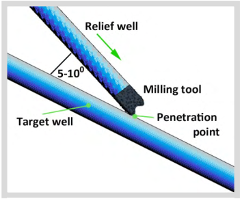
9. As is clear from the diagram above, the final approach section will be steered and yet it is critical that this steering is of the highest accuracy. It is actually better when aiming a milling tool to aim slightly
anticlockwise of the casing center to ensure that the clockwise milling action does not ‘roll off’ the casing on contact. In order to steer accurately when this close to casing, it may be necessary to use GWD on
approach to the final casing shoe especially if the inclination is not close to vertical as the azimuth uncertainty could jeopardies the kill run. After the final casing shoe is in place, there is very little steering
ability and the success of the kill is dependent on accurate placement of the casing.
10. It is worth noting that a relief well contingency plan will be pointless if the original well is not surveyed with sufficient accuracy AND frequency. When the ranging shots are taken, the entire trajectory is shifted
to fit the relative position discovered by ranging. A new relief well plan is generated every time a ranging shot is taken and a new kill point is interpolated in the target well survey. If the original survey is only
available every 500ft, it is impossible to predict where the well will be between surveys and the kill could fail sue to unmeasured doglegs creating unforeseen deviations in the well path.
Post your comment on this topic.