
The MWD error sources were originally set out in reference [1]. Although there have been subsequent revisions to the details of modelling the same basic physical errors still apply.
The original paper identified 34 error sources and at the current state of the model (revision 3) 41 separate MWD error sources have been identified. These can be split into five groups:
1) Sensor errors (This gives a total of 26 MWD sensor error sources)
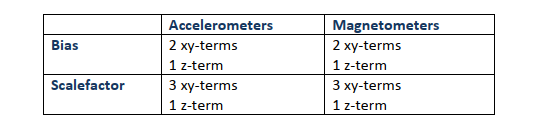
Bias and scalefactor terms are modelled for the accelerometer and magnetometers.
In the original derivation of the paper there was essentially one bias and on scalefactor term for each sensor, however that formulation of the mathematics required an estimate of the toolface angles which couldn’t be
reliably determined at the planning stage. The later revisions introduced toolface independent terms and now the effects of the x and y sensors are lumped together and are not explicitly separated out. For the biases there are still two terms for the x and y directions, however the scale factors are now modelled using three error sources for these two axes.
So for standard MWD surveying there are 14 terms:
The model also covers the situation where an axial interference (or short-collar) correction is applied used to remove the axial effects of BHA magnetic interference. This changes the form of the MWD survey equations and hence the weighting functions and therefore needs to be modelled with a further set of sensor error sources. For axial interference corrections, the z-magnetometer reading is not used and hence a further 12 error sources are defined (14 – (z-mag-bias and z-mag-scale factor).
2) Reference Field Errors (4 error sources)
All MWD survey results are measured relative to the Earth’s magnetic field and uncertainty in this reference leads to survey errors. The magnitude and direction of the Earth’s magnetic field is characterised by it total field strength, declination angle and dip angle and these values are normally obtained from a mathematical model, such as the IGRF or BGGM models, implemented in directional drilling software.
For standard MWD operations, only the declination is important. In order to give an accurate description of the declination uncertainty over the globe, the MWD paper models the declination error with a constant term and with a term which is inversely proportional to the horizontal component of the Earth’s field.
When axial interference corrections are applied to MWD surveys, the reference total field and dip angle terms need to be considered and a further two error sources are identified for these.
3) Interference Errors (2 error sources)
The BHA itself will generally be steel and will have a magnetic field associated with it. Even when non-magnetic drillpipe is built into the BHA, according to industry standard spacing calculations, there will still be a residual effect on the survey results. This is modelled with two error terms, one for constant axial interference and one for direction dependent effects, since constant magnetic interference from the BHA will have an increasing effect on survey azimuth as the wellbore gets closer to a horizontal, magnetic east/west attitude.
4) Misalignment errors (5 error sources)
Following some work done for the gyro error model, the misalignment of the survey tool to the wellbore is now modelled with four misalignment terms. A further term is used to account for sag – the deflection of the BHA under gravity, which leads to an inclination error since the centreline of the survey tool will not be orientated parallel to the borehole axis.
5) Depth errors (4 error sources)
A total of four error sources are used to model the errors in measured depth, due to both random and systematic errors, scale factor errors on the depths and drillpipe stretch under tension from the weight of the BHA.
In this modelling some physical error sources may be lumped together into one error source if in practise it is difficult or unnecessary to separate them. So for example, the misalignment error sources that are identified are for the misalignment of the tool itself to the borehole, not the sensors to the tool. The misalignment of the sensors themselves to the tool axes are accommodated within the sensor bias and scalefactors and are not explicitly separated out.
Post your comment on this topic.