
Downhole survey tools measure their attitude with respect to the Earth’s gravity field and its magnetic or spin field (georeferences). A survey tool’s error model predicts how well the measured field values should agree with the theoretical fields derived as functions of the latitude and depth at which the survey is performed. Compliance of the survey data with these criteria implies compliance with the inclination and azimuth accuracy assumptions of the model. When applied to individual stations this method is very cost effective, since it requires no significant additional data acquisition time and no additional processing effort. However, as will be described, the reliability of this type of test is very dependent on the wellbore and tool attitudes. Detailed mathematical descriptions of
these tests are given in reference 1.
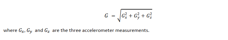
Gravity error test. The measurements provided by three axis (xyz) accelerometer packages can be used to determine the magnitude of the local gravity, in addition to the inclination and toolface of the survey tool. The local gravity () is calculated using the equation:
The local gravity is usually known with high precision, given knowledge of the local latitude, elevation, and vertical depth of the tool. It is therefore possible to calculate the error in the gravity estimate by subtracting the known value of local gravity from the measured value formed using the accelerometer measurements.The gravity estimation error can be used as a QC measure for the accelerometer package performance at each survey station.
The absolute gravity error value is tested against a tolerance level which is related to the error model inputs at a 3σ confidence level. The gravity error test will then classify a survey station as a good station if the
measured gravity error falls within the tolerance interval and as a bad survey station if it falls outside this limit.
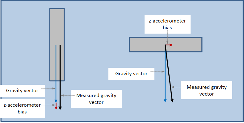
The sensitivity of the gravity error to a particular accelerometer error is dependent on the tool orientation. The inclination and toolface errors created by individual sensor errors are also dependent on tool
orientation. However, the orientation dependency of these errors is different from the gravity error dependency. For example, for a survey tool that is vertical, a z-accelerometer bias has a maximum effect
on calculated total gravity field but a minimum effect on inclination. The converse is the case if the survey tool is horizontal. The large and small differences in the measured gravity field for the vertical
and horizontal tool cases respectively are depicted in below picture .
Detailed analysis of the inclination, toolface and gravity error weighting functions shows that the gravity error test works optimally when the inclination is 45º, and the toolface angle is 45º, 135º, 225º or 315º. In these orientations, the statistical probability that test will indicate a good survey station when the accuracy of both the inclination and toolface estimates are consistent with the error model is greatest. In other words, the results are less likely to be offset by gross accelerometer errors, and indicate a bad survey station when the inclination and/or toolface errors fall outside the limits defined by the error model.
Earth rate tests. Modern north-seeking gyros determine azimuth by measuring orthogonal components of the Earth’s spin vector in a process referred to as gyrocompassing; described in Chapter 9 and 10. Various gyro packages are used and, dependent on the particular sensor configuration adopted, are also capable of providing estimates of the turn rate of the Earth, or the horizontal or vertical component of Earth’s rate. These quantities can therefore be used as gyro quality control measurements in the same manner as the gravity measurement may be used for the accelerometers.
For example, many gyro survey tools use an xy gyro only which provides measurements of the angular rate components about the x and y axes of the survey tool. In addition to the estimation of azimuth, these
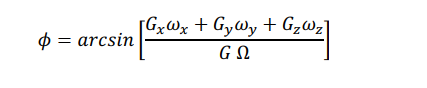
measurements can also be used to generate an estimate of the horizontal component of Earth’s rate using the following equation:
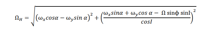
where ωx and ωy are the gyro measurements, ϕ is the local latitude, I is the inclination of the tool and σ is the toolface angle. The true value of this quantity is usually known, and it is therefore possible to calculate a horizontal rate error, ΔΩ = Ω − Ω cos ϕ, and to use this as a gyro QC parameter. Analysis has shown that the reliability of the horizontal Earth rate test is very dependent on the tool orientation, not only inclination and tool face but also azimuth. The horizontal Earth rate test is optimal when the inclination is 45º (or 135º), and the azimuth and toolface are 45º, 135º, 225º or 315º. It becomes singular at both poles, and where the well is vertical or horizontal, and therefore has no value at or close to these locations/orientations. The test has further weaknesses when the survey tool is located in a north/south or an east/west well. Examples are given in SPE 1037341.
For gyro survey tools which provide angular rate measurements about three orthogonal axes, it is possible to conduct additional gyro tests; a total Earth rate test and a latitude test. Unlike the other tests discussed here, the total Earth rate and latitude tests are not described in the QC reference papers1-3.
*Total Earth rate test. *For a stationary xyz gyro tool, the gyro measurements of angular rate about the three orthogonal axes (xyz) can be used to determine the total Earth rate (Ω) using the equation:
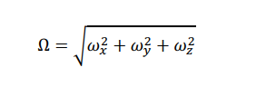
where ωx, ωy and ωz are the three gyro measurements. It is therefore possible to determine the error in the Earth rate estimate and to use this quantity as a gyro package quality control parameter.
Latitude test. For an xyz gyro tool, a further test can be conducted. The dot product of the measured gravitational and Earth rate vectors can be used to provide an estimate of the local latitude. The equation for latitude as a function of the accelerometer and gyro measurements is as follows:
The error in the latitude estimate generated using the gyro and accelerometer measurements is derived by comparing the estimated latitude with the known latitude of the well site. This quantity may then be used as a further quality control parameter for both the gyro and accelerometer packages.
For a survey tool that provides measurements about the xyz axes, the total gravity test controls the accelerometer package performance, the total Earth’s rate test controls the gyro package performance, and the latitude test provides combined control of both sensor packages. Depending on the particular system mechanisation used, the combination of these tests results in a very robust quality control of survey accuracy during operation of the tool, independent of the well trajectory.
Magnetic total field and dip tests. State-of-the-art magnetic instruments make use of xyz magnetometer and xyz accelerometer packages to determine magnetic azimuth; true azimuth is determined subsequently given knowledge of magnetic declination at the well location. Control of the accelerometer package has already been described. It is also necessary to verify the performance of the magnetometer package in order to gain some control of the azimuth estimation process. Magnetometer packages are capable of measuring the Earth’s magnetic field strength (B) and its dip angle (Θ) in addition to the azimuth, where:
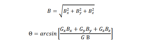
and Bx ,By and Bz are the three magnetometer measurements. These quantities can therefore be used as magnetometer quality control measurements in the same manner as the gyro and accelerometer measurements can be used for the gyros and accelerometers. However, in this case, the same quantities are also used to check the quality of the magnetic reference, as discussed below.
An alternative test is sometimes conducted in which a quality control parameter ∆Btotal-Dip based on a combination of the measurement errors in total field and dip (∆B and ∆Θ) is defined.
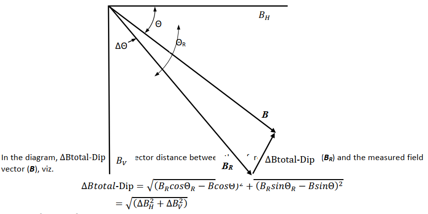
where ∆B2H and ∆B2v are the errors in the horizontal and vertical components of the Earth’s magnetic field. The combined Btotal-Dip test is useful for axially corrected surveys which have one less degree of freedom.
Independent Btotal and Dip tests provide more information with standard surveys.
The magnetometer tests are also subject to some geometrical limitations as occur when using other georeference tests since the various error contributions propagate in a different manner into the azimuth, the total field and the dip measurements. For example, these tests are unable to detect errors on a sensor axis which is aligned with the horizontal east/west direction.
It is noted that using the two Earth’s magnetic field measurements as quality measures is not as straightforward as using the gravity and the Earth’s rate measurements. The Earth’s magnetic field is much more unstable and therefore less predictable than the other two measures. The magnetic tests are therefore required to control the reference itself, in addition to the magnetometer performance. Such tests make use of geo-magnetic models and are strengthened considerably by the application of in-field referencing techniques. However, the total field and dip measurements are unaffected by declination, an error parameter which has a major effect on the calculation of true azimuth. The total field and dip tests can therefore classify a bad survey station as good, even if a gross declination error is present. The azimuth determined using magnetic surveys can never be controlled fully using this type of test.
Post your comment on this topic.