
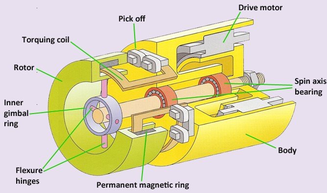
The gyroscope used in Gyrodata tools is known as a dynamically tuned or tuned rotor gyroscope. It has two input axes (denoted x and y) which are mutually orthogonal and which lie in a plane which is perpendicular to the spin (z) axis of the gyroscope. The rotor is connected to the drive shaft by pairs of flexure hinges to an inner gimbal ring. This inner ‘gimbal’ is also connected to the drive shaft by a pair of flexure hinges, the two axes of freedom being mutually orthogonal. This is often called a Hooke’s joint and allows torsional flexibility in two directions (it is noted that this mechanical arrangement constitutes an internal type of gimbal and is far more compact than the external gimbal structure shown in Figure 51). At the other end of the drive shaft is a synchronous motor. The gyro derives its name from the rotor suspension mechanism which theoretically allows the rotor to become decoupled from the drive shaft at a certain tuned speed; typically in excess of 12,000 rpm. The rotor contains permanent magnets which set up a radial magnetic field within the assembly.
In the presence of an applied turn rate which causes a displacement of the rotor with respect to the case of the gyro, the spin axis of a rotor is made to precess back to the ‘null’ position by the application of a suitable torque. A very accurate angular measurement can be made, provided that the torque required to null the deflection can be generated and measured. The mechanism by which this is achieved is outlined below.
The angular position of the rotor is sensed by pick-offs attached to the case of the gyroscope. When rotor deflection occurs, the resulting pick-off signals are sent to the gyro servo electronics which in turn drives currents through the torquer coils. The interaction of the magnetic field generated by these currents with the field produced by the rotor magnets produces forces on the rotor which cause it to precess and so drive its deflection to zero. When the system is ‘balanced’, the currents in the torquer coils provide a direct measure of the angular rate to which the gyro is subjected.
This application of the precession principle enables very accurate measurements to be made of the rate of turn of the case of the gyroscope. The torque re-balance technique described is fundamental to the application of inertial measurement systems in which the sensors are attached rigidly to the survey tool (often referred to as strapdown systems) as employed in Gyrodata tools. The application of a rate gyroscope to determine the azimuth of a borehole relies on measurement of the Earth’s rate of turn, which forms the subject of the following section.
Post your comment on this topic.