
The different planes
Measurements taken and files produced with Flexijet and the FlexiCAD software are most commonly done using planes. A plane can be pictured as a virtual infinite surface upon which measurements are set. All measurements that are made with Flexijet are translated perpendicular to the current plane.
Working with planes has the following advantages:
- The measurements are more precise because we can choose measurement points for optimum clarity that will be projected to the plane rather than needing to get the exact corners of objects
- The editing of measured objects, such as trimming, stretching, rounding and so on, is possible when the objects (lines, arcs) are on one plane.
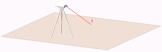
Horizontal plane
![]()

A horizontal plane defines an infinite surface that is parallel to the horizon.
Picture a large horizontal surface. You could move it upwards to the sky and down to the floor. Only one measurement point is required to set a level horizonal plane. This one point determines the height of the horizontal plane. Horizontal planes are used when it can be assumed that the surface is almost horizontal. The floorplan of a room, a countertop surface, and a flat ceiling are generally measured with a horizontal plane. If the floor has been defined as a horizontal plane, for example, you would take all measurements on the walls as close to the floor as possible. The measured point is projected onto that plane by FlexiCAD.
Setting a Horizontal Plane
In the Project Explorer, click to select the folder for which you want to define a plane. In the Measurement tab, in the group Planes, click on Horizontal Plane
![]()
In the command window, you will be prompted to measure a single point on the surface you wish to measure.
If measuring a floor, this plane would typically be set with a single point on the floor. Or just by clicking in the canvas are if you are editing.
Note: Horizontal planes are always viewed from the top, or plan view! It’s a good practice to leave a note on a horizontal plane, such as a shower ceiling, to remember to mirror or flip this plane prior to fabricating!
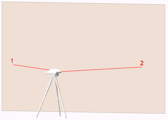
Vertical plane
![Vertical Plane Icon]()

A vertical plane is a plane that is perpendicular to the horizon, such as a vertical wall. It is basically a precisely aligned wall that stretches from the ground straight to the sky.
A vertical plane is always defined with two points. The two points should be as far apart horizontally (from left to right) as possible and cannot be measured above each other. Vertical planes are used for measuring walls, doors, waterfalls, full-height backsplashes, or windows.

Setting a Vertical Plane
In Project Explorer, click to select the folder for which you want to define a plane. In the Measurement tab, in the group Planes, click on Vertical Plane.
![]()
In the command window, you will be prompted to measure the first point on the left and then the second point on the right.
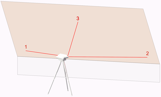
Free plane
![Free plane icon]()

A free plane is a plane that can be oriented in any direction. A free plane can be a roof slope, for example, which you can picture as an infinite flat surface with the pitch of the roof.
A free plane is set with 3 points, which span a preferably large triangle.

Setting a Free Plane
In the Project Explorer, click to select the folder for which you want to define a plane. In the Measurement tab, in the group Planes, click on Free.
Plane.
![]()
In the command window, you will be prompted to measure the first point on the bottom left, then the second point on the bottom right, and the third point on the top (center).
Redefine Plane
The ‘Redefine Plane’ function redefines a folder’s plane. Note that this does not change the position of elements—just the folder itself.
This function can be used to reverse the view of a vertical folder, for example.
Flattening all elements on a plane.
In FlexiCAD 3.1 and later, the function ‘2D-Projection’ will flatten all elements in the current folder to the current plane. This is useful if elements were traced from another folder in 3D-snap mode, instead of 2D-snap mode. Learn more about 2D-Projection here.
Post your comment on this topic.