
The Flexijet stair function is a powerful tool for creating as-built staircase measurements without measuring each piece individually. This function also allows for the measurement of stairs to be exported to Stair construction softwares such as Compass.
For more information or help, please call our support line 1-844-MY-FLEXI (1-844-693-5394) ext 2 for support.
Basic Stair measurements
To build a 3D staircase using the Stair function, a minimum of 3 areas must be measured:
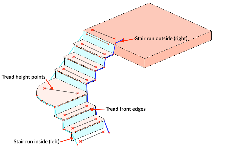
- Inside and outside edges of the staircase
- Front edges of the treads (The back edges of treads are optional)
- Heights of the treads
Additionally, the following conditions must be met:
- Stair front and back edges must be straight. Staircases with arced front edges must be measured without the stair function
- Stair tread front edges must not overlap
- Split/bifurcated staircase sections must be organized into separate 3D subfolders
Measuring stairs with Flexijet:
- Set Flexijet 3D in a position that has a good line-of-sight to as many stairs as possible. As usual, you can Reposition Flexijet during the measurement.
- Begin the measurement as usual, Auto-Levelling the Flexijet as usual, Align to object with an origin point (Using 3 points), and create a project folder.
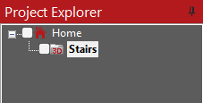
- Create a 3D folder for the stairs.
![]()
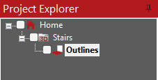
- Within that 3D folder, create a Horizontal folder and set the plane on the ground. The name can be anything, such as ‘Outlines’.
![]()
- In that 2D folder you have created, measure the inner and outer walls of the stairwell using the polyline function. NOTE: these lines must extend before and beyond the tread front edges.
![]()
- In the same 2D folder, measure the front edges of the stair treads using ‘Multiple Lines’ for straight front edges. Also, measure the tread edge of the top stair (edge of landing).
![]()
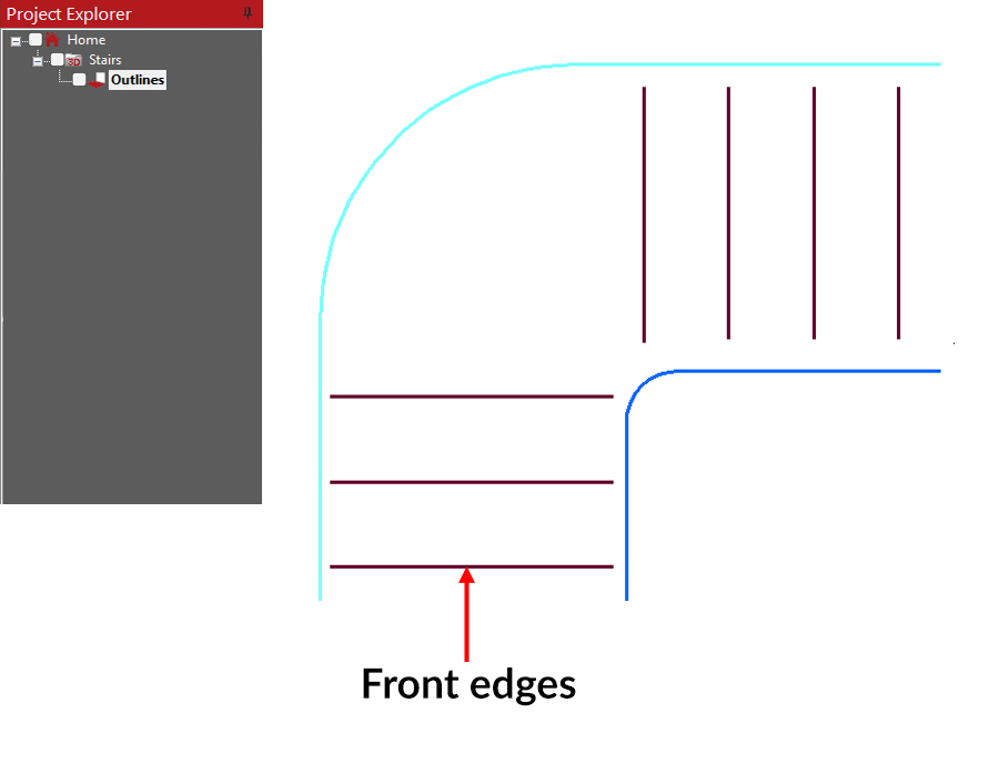
- Optional: Create an additional horizontal folder and measure the back edges of the stair treads using the ‘Multiple lines’ function. Tread back edges are optional.
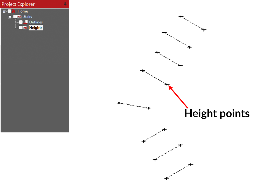
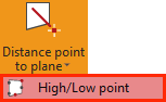
- In the 3D folder for the stairs (which might be called ‘Stairs’), create another folder for tread heights called ‘Heights.’ Measure the heights of the individual treads, including the landing at the bottom (where you set your plane) and the landing at the top. To do this, you may use either the ‘Points’ function and measure 1 point per stair, or multiple points on each stair using the ‘High/low point’ function (located under the ‘Distance Point to Plane’ button on the Measurement ribbon) for a better accuracy. Measure these points on the top of the treads.
![]()
![]()
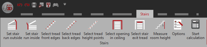
Creating the 3D stairs with the Stair function.
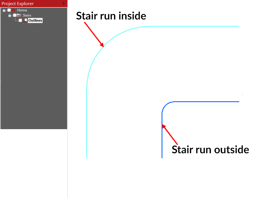
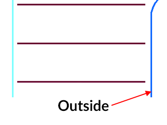
- Go to your 2D folder, ‘Outline’. On the Stair ribbon, choose the ‘Set stair run outside’ button and select the line/polyline for the Right side wall of the stairs. This will convert that element to a Polyline and its colour to Blue. If you hover over the line, the line will be identified as the ‘Stair wall outside’. Ensure that this line extends past the bottom and top stair treads.
![]()
![]()

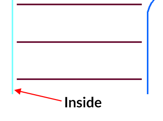
- On the Stair ribbon, choose the ‘Set stair run inside’ button and select the line/polyline for the Left side wall of the stairs. This will convert that element to a Polyline and its colour to turquoise. If you hover over the line, the line will be identified as the ‘Stair wall inside’. Ensure that this line extends past the bottom and top stair treads.
![]()
![]()

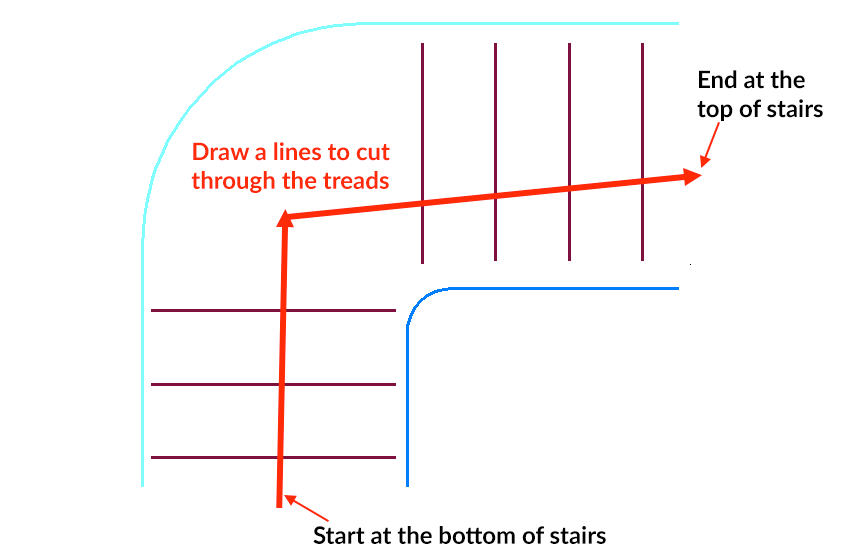
- On the Stair ribbon, choose the function ‘Select tread front edges’. This tool uses a line in the direction of the stairs from bottom to top. You will click below the bottom step, then click above the top step to essentially draw a line through the stair treads. If your staircase changes direction, such as through a landing, you may click a 3rd point (and additional points if required) to draw a multi-segmented line through all the risers, from bottom to top. Press ‘Enter’ to continue.
![]()
![]()

- If you measured the back edges of the treads earlier, repeat this step to select the back edges. Stair tread back edges are not required to complete the stair calculation.
![]()

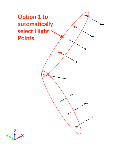
- Select your ‘Heights’ folder, then choose ‘Select tread height points’ from the ‘Stairs’ ribbon. Follow the prompts in the command window (1=high points, 2=low points, 3=select manually). Options 1 or 2 will automatically select from the sets of High/low points measured on each tread. Option 3 requires manually selecting the points to be used.
![]()
![]()

- Now, select your 3d ‘Stairs’ folder and choose ‘Options’ from the Stairs ribbon. From this menu, you may select the tread overhangs and other options.
![]()
![Stair options window]()


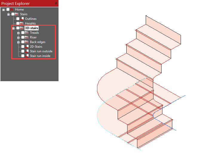
- Click ‘Start Calculation’ to run the Stairs calculation.
![]()
![]()

Watch the video tutorial!
Feedback
Copyright © 2025 Flexijet GmbH
—
Powered by 
Post your comment on this topic.