
PLC Developers Guide / PLC I/O Mode Control / PLC Inputs for PLC I/O Mode /
Right Motor Status |
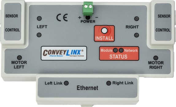
ConveyLinx ERSC ✅ | ConveyLinx-Ai 24V ✅ | ConveyLinx-Ai 48V ✅ |
 |
 |
 |
|
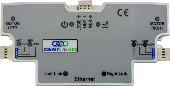
| ConveyLinx-ECO ✅ | ZPA Mode ❌ | PLC I/O Mode ✅ | |
 |
 |
 |
| Register Name | Internal Address | Assembled PLC Address | Description | ||
| Right Motor Current | 4:0079 | M: 4:1708 E: I.Data [8] P: Byte 16 (Hi) P: Byte 17 (Lo) |
Integer Value | ||
| Right Motor Current in mA | |||||
| Example: 1900 = 1.9 Amps | |||||
| Right Motor Frequency | 4:0080 | M: 4:1709 E: I.Data [9] P: Byte 18 (Hi) P: Byte 19 (Lo) |
Integer Value | ||
| Right Motor electrical frequency in Hz | |||||
| Example: 300 = 300 Hz | |||||
| Right Motor Temperature | 4:0081 | M: 4:1710 E: I.Data [10] P: Byte 20 (Hi) P: Byte 21 (Lo) |
Byte-Wise Integer Value | ||
| Byte encoded value of temperatures in °C | |||||
| High Byte = Right Motor temperature | |||||
| Low Byte = Internal Right Motor Driver temperature | |||||
| Right Motor Status | 4:0082 | M: 4:1711 E: I.Data [11] P: Byte 22 (Hi) P: Byte 23 (Lo) |
Bitwise Value | ||
| Bit 00 = | Motor Rotation Status | ||||
| Bit 01 = | Motor Rotation Status | ||||
| Bit 02 = | Port in Digital Mode | ||||
| Bit 03 = | Reserved | ||||
| Bit 04 = | Reserved | ||||
| Bit 05 = | Board Overheat | ||||
| Bit 06 = | Over-Voltage | ||||
| Bit 07 = | Low Voltage | ||||
| Bit 08 = | Over-Heated | ||||
| Bit 09 = | Over-Current | ||||
| Bit 10 = | Short Circuit | ||||
| Bit 11 = | Motor Not Connected | ||||
| Bit 12 = | Overloaded | ||||
| Bit 13 = | Stalled | ||||
| Bit 14 = | Hall Sensor Error | ||||
| Bit 15 = | 2 See Note | ||||
| 1 Real Speed Right Motor |
4:0508 | M: 4:1724 E: I.Data [24] P: Byte 48 (Hi) P: Byte 49 (Lo) |
1 Motor Speed and Speed Status | ||
| Bit 00 – Bit 13 = Numerical value of Right motor’s current speed | |||||
| ● For MDR value is in mm/sec | |||||
| ● For PGD value is in RPM x 10 | |||||
| Bit 14 = Set when Right Motor speed is above its maximum speed | |||||
| Bit 15 = Set when Right Motor speed is below its minimum speed | |||||
1 Motor Speed and Speed Status is only available for ConveyLinx-Ai Family controllers.