
PLC Developers Guide / PLC I/O Mode Control / PLC Outputs for PLC I/O Mode / Complete List of PLC IO Output Assembly
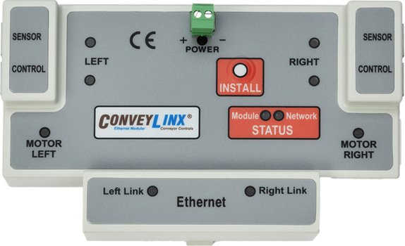
ConveyLinx-ERSC Family
PLC I/O Output Assembly |
ConveyLinx ERSC ✅ | ConveyLinx-Ai 24V ❌ | ConveyLinx-Ai 48V ❌ |
 |
 |
 |
|
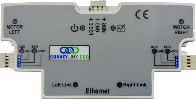
| ConveyLinx-ECO ❌ | ZPA Mode ❌ | PLC I/O Mode ✅ | |
 |
 |
 |
| Register Name | Internal Address | Assembled PLC Address | Description | ||
| ConveyStop Command | 4:0020 | M: 4:1800 E: O.Data [0] P: Byte 0 (Hi) P: Byte 1 (Lo) |
Integer Value | ||
| 0 = | No Command | ||||
| 1 = | Command local module’s Stop Group to go to Stopped State | ||||
| 2 = | Command local module’s Stop Group to Clear Stopped State | ||||
| Set Digital Control Left Motor Port |
4:0060 | M: 4:1801 E: O.Data [1] P: Byte 2 (Hi) P: Byte 3 (Lo) |
Bitwise Value | ||
| Bit 00 = | Energize Left Motor Port Pin 3 | ||||
| Bit 01 = | Energize Left Motor Port Pin 4 | ||||
| Bit 02 = | Energize Left Motor Port Pin 5 | ||||
| Bit 03 = | Reserved | ||||
| Bit 04 = | Reserved | ||||
| Bit 05 = | Reserved | ||||
| Bit 06 = | Brake Output Pin 9 | ||||
| Bit 07 = | Enable Brake Pin 9 when Left Motor Port is NOT in Digital Mode | ||||
| Bit 08 = | Clear over-current error | ||||
| Bit 09 = | Reserved | ||||
| Bit 10 = | Reserved | ||||
| Bit 11 = | Reserved | ||||
| Bit 12 = | Reserved | ||||
| Bit 13 = | Reserved | ||||
| Bit 14 = | Reserved | ||||
| Bit 15 = | Digital Output Mode Enable | ||||
| 0 = Use Left Motor Port for Motor Control | |||||
| 1 = Use Left Motor Port as Digital Outputs | |||||
| Set Digital Control Right Motor Port |
4:0084 | M: 4:1802 E: O.Data [2] P: Byte 4 (Hi) P: Byte 5 (Lo) |
Bitwise Value | ||
| Bit 00 = | Energize Right Motor Port Pin 3 | ||||
| Bit 01 = | Energize Right Motor Port Pin 4 | ||||
| Bit 02 = | Energize Right Motor Port Pin 3 | ||||
| Bit 03 = | Reserved | ||||
| Bit 04 = | Reserved | ||||
| Bit 05 = | Reserved | ||||
| Bit 06 = | Brake Output Right Motor Port Pin 9 | ||||
| Bit 07 = | Enable Brake Pin 9 when Right Motor Port is NOT in Digital Mode | ||||
| Bit 08 = | Clear over-current error | ||||
| Bit 09 = | Reserved | ||||
| Bit 10 = | Reserved | ||||
| Bit 11 = | Reserved | ||||
| Bit 12 = | Reserved | ||||
| Bit 13 = | Reserved | ||||
| Bit 14 = | Reserved | ||||
| Bit 15 = | Digital Output Mode Enable | ||||
| 0 = Use Right Motor Port for Motor Control | |||||
| 1 = Use Right Motor Port as Digital Outputs | |||||
| Control Port Digital Output Control | 4:0037 | M: 4:1803 E: O.Data [3] P: Byte 6 (Hi) P: Byte 7 (Lo) |
Bitwise Value | ||
| Bit 00 = | Reserved | ||||
| Bit 01 = | Left Control Port Output | ||||
| Bit 02 = | Reserved | ||||
| Bit 03 = | Right Control Port Output | ||||
| All other Bits reserved | |||||
| Run / Reverse Left Motor |
4:0260 | M: 4:1804 E: O.Data [4] P: Byte 8 (Hi) P: Byte 9 (Lo) |
Bitwise Value | ||
| Bit 00 : | |||||
| 1 = Run Command | |||||
| 0 = Stop Command | |||||
| Bit 08 : | |||||
| 0 = Run in Configured Direction | |||||
| 1 = Run opposite of Configured Direction | |||||
| Set Brake Method Left Motor |
4:0261 | M: 4:1805 E: O.Data [5] P: Byte 10 (Hi) P: Byte 11 (Lo) |
Integer Value | ||
| 1 = | Use Standard Brake Method | ||||
| 2 = | Use Free Coast Brake Method | ||||
| 3 = | Use Servo Brake 1 Method | ||||
| 4 = | Use Servo Brake 2 Method | ||||
| 0 = | Remain at last configured or last value entered | ||||
| Set Slave Mode Left Motor |
4:0262 | M: 4:1806 E: O.Data [6] P: Byte 12 (Hi) P: Byte 13 (Lo) |
Byte-Wise Integer Value | ||
| Low Byte Value | |||||
| 0 = Remain at last configured or last value entered | |||||
| 1 = Use Open Loop | |||||
| 1 = Use Closed Loop | |||||
| High Byte Value | |||||
| 0 = Ignore | |||||
| 1 = Slave Mode OFF | |||||
| 2 = Slave Mode ON – Left = Right | |||||
| 3 = Slave Mode ON – Left opposite of Right | |||||
| Run / Reverse Right Motor |
4:0270 | M: 4:1807 E: O.Data [7] P: Byte 14 (Hi) P: Byte 15 (Lo) |
Bitwise Value | ||
| Bit 00 : | |||||
| 1 = Run Command | |||||
| 0 = Stop Command | |||||
| Bit 08 : | |||||
| 0 = Run in Configured Direction | |||||
| 1 = Run opposite of Configured Direction | |||||
| Set Brake Method Right Motor |
4:0271 | M: 4:1808 E: O.Data [8] P: Byte 16 (Hi) P: Byte 17 (Lo) |
Integer Value | ||
| 1 = | Use Standard Brake Method | ||||
| 2 = | Use Free Coast Brake Method | ||||
| 3 = | Use Servo Brake 1 Method | ||||
| 4 = | Use Servo Brake 2 Method | ||||
| 0 = | Remain at last configured or last value entered | ||||
| Set Slave Mode Right Motor |
4:0272 | M: 4:1809 E: O.Data [9] P: Byte 18 (Hi) P: Byte 19 (Lo) |
Byte-wise Integer Value | ||
| Low Byte Value | |||||
| 0 = Remain at last configured or last value entered | |||||
| 1 = Use Open Loop | |||||
| 1 = Use Closed Loop | |||||
| High Byte Value | |||||
| 0 = Ignore | |||||
| 1 = Slave Mode OFF | |||||
| 2 = Slave Mode ON – Right = Left Motor | |||||
| 3 = Slave Mode ON – Right opposite of Left | |||||
| Set Speed Reference Left Motor |
4:0040 | M: 4:1810 E: O.Data [10] P: Byte 20 (Hi) P: Byte 21 (Lo) |
Integer Value | ||
| Value = | 0.1% increments of max speed | ||||
| Range = | 0 to 1000 | ||||
| Example: 400 = 40% of Max PWM | |||||
| 0 = | Remain at last non-zero value entered | ||||
| Set Speed Reference Right Motor |
4:0064 | M: 4:1811 E: O.Data [11] P: Byte 22 (Hi) P: Byte 23 (Lo) |
Integer Value | ||
| Value = | 0.1% increments of max speed | ||||
| Range = | 0 to 1000 | ||||
| Example: 400 = 40% of Max PWM | |||||
| 0 = | Remain at last non-zero value entered | ||||
| Set Acceleration Left Motor |
4:0043 | M: 4:1812 E: O.Data [12] P: Byte 24 (Hi) P: Byte 25 (Lo) |
Integer Value | ||
| When Speed Control is Open Loop: | |||||
| Value = | msec | ||||
| Range = | 30 to 10000 | ||||
| Example: 900 = 0.9 sec | |||||
| When Speed Control is Closed Loop: | |||||
| Value = | Motor Pulses | ||||
| Range = | 30 to 10000 | ||||
| For Either Open or Closed Loop: | |||||
| 0 = | Remain at last non-zero value entered | ||||
| Set Deceleration Left Motor |
4:0044 | M: 4:1813 E: O.Data [13] P: Byte 26 (Hi) P: Byte 27 (Lo) |
Integer Value | ||
| When Speed Control is Open Loop: | |||||
| Value = | msec | ||||
| Range = | 0 to 10000 | ||||
| Example: 900 = 0.9 sec | |||||
| When Speed Control is Closed Loop: | |||||
| Value = | Motor Pulses | ||||
| Range = | 0 to 10000 | ||||
| For Either Open or Closed Loop: | |||||
| 0 = | Remain at last non-zero value entered | ||||
| Set Acceleration Right Motor |
4:0067 | M: 4:1814 E: O.Data [14] P: Byte 28 (Hi) P: Byte 29 (Lo) |
Integer Value | ||
| When Speed Control is Open Loop: | |||||
| Value = | msec | ||||
| Range = | 30 to 10000 | ||||
| Example: 900 = 0.9 sec | |||||
| When Speed Control is Closed Loop: | |||||
| Value = | Motor Pulses | ||||
| Range = | 30 to 10000 | ||||
| For Either Open or Closed Loop: | |||||
| 0 = | Remain at last non-zero value entered | ||||
| Set Deceleration Right Motor |
4:0068 | M: 4:1815 E: O.Data [15] P: Byte 30 (Hi) P: Byte 31 (Lo) |
Integer Value | ||
| When Speed Control is Open Loop: | |||||
| Value = | msec | ||||
| Range = | 0 to 10000 | ||||
| Example: 900 = 0.9 sec | |||||
| When Speed Control is Closed Loop: | |||||
| Value = | Motor Pulses | ||||
| Range = | 0 to 10000 | ||||
| For Either Open or Closed Loop: | |||||
| 0 = | Remain at last non-zero value entered | ||||
| Clear Motor Error | 4:0022 | M: 4:1816 E: O.Data [16] P: Byte 32 (Hi) P: Byte 33 (Lo) |
Integer Value | ||
| 1 = | Send Reset command | ||||
| 0 = | Clear Reset command | ||||
| Set Status to Downstream Module |
4:0196 | M: 4:1817 E: O.Data [17] P: Byte 34 (Hi) P: Byte 35 (Lo) |
Integer Value | ||
| Used to write this module’s ZPA Status to its neighboring Downstream module | |||||
| 4 = | Instruct Downstream module to “wake-up” and run its most upstream zone | ||||
| 1 = | Instructs Downstream module that carton has exited local zone and to accept any tracking data written in Set Discharge Tracking Word 1 / Word 2 registers when carton arrives | ||||
| Set Status to Upstream Module |
4:0116 | M: 4:1818 E: O.Data [18] P: Byte 36 (Hi) P: Byte 37 (Lo) |
Integer Value | ||
| Used to write this module’s ZPA Status to its neighboring Upstream module | |||||
| 5 = | Instructs Upstream module’s discharge zone to accumulate and hold any carton that arrives at its discharge zone | ||||
| 1 = | Instructs Upstream module’s discharge zone to release any carton that arrives at its discharge zone | ||||
| Set Sensor/Control Port Input Signal Condition Mask |
4:0034 | M: 4:1819 E: O.Data [19] P: Byte 38 (Hi) P: Byte 39 (Lo) |
Bitwise Value | ||
| Bit 00 = | Left Sensor Port – Pin 3 | ||||
| Bit 01 = | Left Control Port – Pin 3 | ||||
| Bit 02 = | Right Sensor Port – Pin 3 | ||||
| Bit 03 = | Right Control Port – Pin 3 | ||||
| Bit 04 = | Left Sensor Port – Pin 4 | ||||
| Bit 05 = | Left Control Port – Pin 4 | ||||
| Bit 06 = | Right Sensor Port – Pin 4 | ||||
| Bit 07 = | Right Control Port – Pin 4 | ||||
| All other Bits reserved | |||||
| Set Discharge Tracking Word 1 | 4:0201 | M: 4:1820 E: O.Data [20] P: Byte 40 (Hi) P: Byte 41 (Lo) |
Integer Value | ||
| Only used when local PLC I/O Mode module needs to pass tracking data Word 1 to a downstream connected ConveyLinx Module. Used in conjunction with Set Status to Downstream Module register | |||||
| Set Discharge Tracking Word 2 | 4:0202 | M: 4:1821 E: O.Data [21] P: Byte 42 (Hi) P: Byte 43 (Lo) |
Integer Value | ||
| Only used when local PLC I/O Mode module needs to pass tracking data Word 2 to a downstream connected ConveyLinx Module. Used in conjunction with Set Status to Downstream Module register | |||||
| Reserved | N/A | M: 4:1822 E: O.Data [22] P: Byte 44 (Hi) P: Byte 45 (Lo) |
Reserved | ||
| Set Servo Position Value Left Motor |
4:0008 | M: 4:1823 E: O.Data [23] P: Byte 46 (Hi) P: Byte 47 (Lo) |
Signed Integer Value | ||
| Value of the position to move to on the next Left Motor Servo Run Command | |||||
| MDR = | Value is in Motor Pulses | ||||
| PGD = | Value is in Motor Pulses | ||||
| Range = | -32767 to +32767 | ||||
| Set Servo Command Word Left Motor |
4:0009 | M: 4:1824 E: O.Data [24] P: Byte 48 (Hi) P: Byte 49 (Lo) |
Bitwise Value | ||
| Bit 00 = | Set Bit to Reset Left Motor Servo Position Value to 0 | ||||
| Bit 01 = | Set to Initiate Run Left Motor to position set in the Left Motor Servo Position Value Register | ||||
| All other Bits reserved | |||||
| Set Servo Position Value Right Motor |
4:0013 | M: 4:1825 E: O.Data [25] P: Byte 50 (Hi) P: Byte 51 (Lo) |
Signed Integer Value | ||
| Value of the position to move to on the next Right Motor Servo Run Command | |||||
| MDR = | Value is in Motor Pulses | ||||
| PGD = | Value is in Motor Pulses | ||||
| Range = | -32767 to +32767 | ||||
| Set Servo Command Word Right Motor |
4:0014 | M: 4:1826 E: O.Data [26] P: Byte 52 (Hi) P: Byte 53 (Lo) |
Bitwise Value | ||
| Bit 00 = | Set Bit to Reset Right Motor Servo Position Value to 0 | ||||
| Bit 01 = | Set to Initiate Run Right Motor to position set in the Left Motor Servo Position Value Register | ||||
| All other Bits reserved | |||||