
PLC Developers Guide / PLC I/O Mode Control / PLC Inputs for PLC I/O Mode /
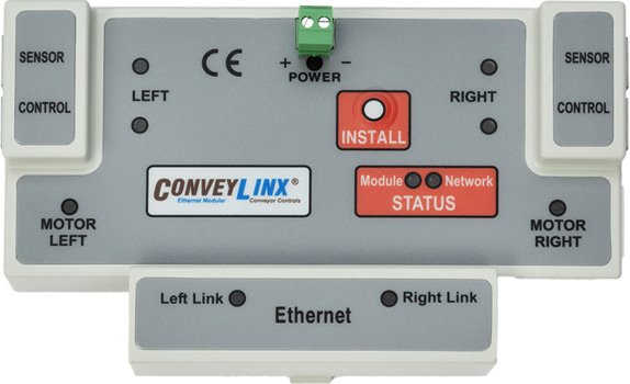
ERSC Family
PLC I/O Input Assembly |
ConveyLinx ERSC ✅ | ConveyLinx-Ai 24V ❌ | ConveyLinx-Ai 48V ❌ |
 |
 |
 |
|
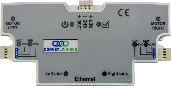
| ConveyLinx-ECO ❌ | ZPA Mode ❌ | PLC I/O Mode ✅ | |
 |
 |
 |
| Register Name | Internal Address | Assembled PLC Address | Description | ||
| ConveyStop Status | 4:0019 | M: 4:1700 E: I.Data [0] P: Byte 0 (Hi) P: Byte 1 (Lo) |
Bitwise Value | ||
| Bit 00 = | Reserved | ||||
| Bit 01 = | Reserved | ||||
| Bit 02 = | Reserved | ||||
| Bit 03 = | Reserved | ||||
| Bit 04 = | Reserved | ||||
| Bit 05 = | Stop Active on another module in Stop Group | ||||
| Bit 06 = | Stop Active due to lost communication connection | ||||
| Bit 07 = | Stop Active due to lost PLC connection | ||||
| Bit 08 = | Stop active on Left Control Port | ||||
| Bit 09 = | Stop active on Right Control Port | ||||
| Bit 10 = | Stop Active due to lost PLC connection | ||||
| Bit 11 = | Reserved | ||||
| Bit 12 = | Reserved | ||||
| Bit 13 = | Reserved | ||||
| Bit 14 = | Reserved | ||||
| Bit 15 = | Reserved | ||||
| Sensor Port Inputs | 4:0035 | M: 4:1701 E: I.Data [1] P: Byte 2 (Hi) P: Byte 3 (Lo) |
Bitwise Value | ||
| Bit 00 = | Left Sensor Port – Pin 3 | ||||
| Bit 01 = | Left Control Port – Pin 3 | ||||
| Bit 02 = | Right Sensor Port – Pin 3 | ||||
| Bit 03 = | Right Control Port – Pin 3 | ||||
| Bit 04 = | Left Sensor Port – Pin 4 | ||||
| Bit 05 = | Left Control Port – Pin 4 | ||||
| Bit 06 = | Right Sensor Port – Pin 4 | ||||
| Bit 07 = | Right Control Port – Pin 4 | ||||
| Bit 08 = | Reserved | ||||
| Bit 09 = | Reserved | ||||
| Bit 10 = | Reserved | ||||
| Bit 11 = | Reserved | ||||
| Bit 12 = | Reserved | ||||
| Bit 13 = | Reserved | ||||
| Bit 14 = | Reserved | ||||
| bit 15 = | 2 sec ON / 2 sec OFF heartbeat | ||||
| Sensor Detect | 4:0036 | M: 4:1702 E: I.Data [2] P: Byte 4 (Hi) P: Byte 5 (Lo) |
Bitwise Value | ||
| Bit 00 = | Device is connected to Right Sensor Port | ||||
| Bit 01 = | Device is connected to Left Sensor Port | ||||
| Bit 02 – Bit 15 = Reserved | |||||
| Motor Voltage | 4:0024 | M: 4:1703 E: I.Data [3] P: Byte 6 (Hi) P: Byte 7 (Lo) |
Integer Value | ||
| Module Input Voltage Value in mV | |||||
| Range: 0 to 35000 | |||||
| Example: 23500 = 23.5V | |||||
| Left Motor Current | 4:0055 | M: 4:1704 E: I.Data [4] P: Byte 8 (Hi) P: Byte 9 (Lo) |
Integer Value | ||
| Left Motor Current in mA | |||||
| Example: 1900 = 1.9 Amps | |||||
| Left Motor Frequency | 4:0056 | M: 4:1705 E: I.Data [5] P: Byte 10 (Hi) P: Byte 11 (Lo) |
Integer Value | ||
| Left Motor electrical frequency in Hz | |||||
| Example: 300 = 300 Hz | |||||
| Left Motor Temperature | 4:0057 | M: 4:1706 E: I.Data [6] P: Byte 12 (Hi) P: Byte 13 (Lo) |
Byte-Wise Integer Value | ||
| Byte encoded value of temperatures in °C | |||||
| High Byte = Calculated Left Motor temperature | |||||
| Low Byte = Internal Left Motor Driver temperature | |||||
| Left Motor Status | 4:0058 | M: 4:1707 E: I.Data [7] P: Byte 14 (Hi) P: Byte 15 (Lo) |
Bitwise Value | ||
| Bit 00 = | Motor Rotation Status | ||||
| Bit 01 = | Motor Rotation Status | ||||
| Bit 02 = | Port in Digital Mode | ||||
| Bit 03 = | Reserved | ||||
| Bit 04 = | Reserved | ||||
| Bit 05 = | Board Overheat | ||||
| Bit 06 = | Over-Voltage | ||||
| Bit 07 = | Low Voltage | ||||
| Bit 08 = | Over-Heated | ||||
| Bit 09 = | Over-Current | ||||
| Bit 10 = | Short Circuit | ||||
| Bit 11 = | Motor Not Connected | ||||
| Bit 12 = | Overloaded | ||||
| Bit 13 = | Stalled | ||||
| Bit 14 = | Hall Sensor Error | ||||
| Bit 15 = | Motor Not Used | ||||
| Right Motor Current | 4:0079 | M: 4:1708 E: I.Data [8] P: Byte 16 (Hi) P: Byte 17 (Lo) |
Integer Value | ||
| Right Motor Current in mA | |||||
| Example: 1900 = 1.9 Amps | |||||
| Right Motor Frequency | 4:0080 | M: 4:1709 E: I.Data [9] P: Byte 18 (Hi) P: Byte 19 (Lo) |
Integer Value | ||
| Right Motor electrical frequency in Hz | |||||
| Example: 300 = 300 Hz | |||||
| Right Motor Temperature | 4:0081 | M: 4:1710 E: I.Data [10] P: Byte 20 (Hi) P: Byte 21 (Lo) |
Byte-Wise Integer Value | ||
| Byte encoded value of temperatures in °C | |||||
| High Byte = Calculated Right Motor temperature | |||||
| Low Byte = Internal Right Motor Driver temperature | |||||
| Right Motor Status | 4:0082 | M: 4:1711 E: I.Data [11] P: Byte 22 (Hi) P: Byte 23 (Lo) |
Bitwise Value | ||
| Bit 00 = | Motor Rotation Status | ||||
| Bit 01 = | Motor Rotation Status | ||||
| Bit 02 = | Port in Digital Mode | ||||
| Bit 03 = | Reserved | ||||
| Bit 04 = | Reserved | ||||
| Bit 05 = | Board Overheat | ||||
| Bit 06 = | Over-Voltage | ||||
| Bit 07 = | Low Voltage | ||||
| Bit 08 = | Over-Heated | ||||
| Bit 09 = | Over-Current | ||||
| Bit 10 = | Short Circuit | ||||
| Bit 11 = | Motor Not Connected | ||||
| Bit 12 = | Overloaded | ||||
| Bit 13 = | Stalled | ||||
| Bit 14 = | Hall Sensor Error | ||||
| Bit 15 = | Motor Not Used | ||||
| Left Motor Port Digital I/O Status |
4:0060 | M: 4:1712 E: I.Data [12] P: Byte 24 (Hi) P: Byte 25 (Lo) |
Bitwise Value | ||
| Bit 12 = | Short Circuit Error on one or more coil output pins | ||||
| Bit 14 = | Over Current – More than 1A detected on one or more coil output pins | ||||
| All other Bits reserved | |||||
| Right Motor Port Digital I/O Status |
4:0084 | M: 4:1713 E: I.Data [13] P: Byte 26 (Hi) P: Byte 27 (Lo) |
Bitwise Value | ||
| Bit 12 = | Short Circuit Error on one or more coil output pins | ||||
| Bit 14 = | Over Current – More than 1A detected on one or more coil output pins | ||||
| All other Bits reserved | |||||
| Module Status Upstream |
4:0134 | M: 4:1714 E: I.Data [14] P: Byte 28 (Hi) P: Byte 29 (Lo) |
Integer value of Low or High Byte | ||
| 0×01 = | Zone sensor clear and motor stopped | ||||
| 0×02 = | Zone sensor clear, motor running, accepting from upstream zone | ||||
| 0×04 = | Zone sensor blocked, motor running, discharging to downstream zone | ||||
| 0×05 = | Zone sensor blocked and motor stopped | ||||
| 0×06 = | Busy (state during ConveyStop active mode) | ||||
| Module Status Downstream |
4:0232 | M: 4:1715 E: I.Data [15] P: Byte 30 (Hi) P: Byte 31 (Lo) |
Integer value of Low or High Byte | ||
| 0×01 = | Zone sensor clear and motor stopped | ||||
| 0×02 = | Zone sensor clear, motor running, accepting from upstream zone | ||||
| 0×04 = | Zone sensor blocked, motor running, discharging to downstream zone | ||||
| 0×05 = | Zone sensor blocked and motor stopped | ||||
| 0×06 = | Busy (state during ConveyStop active mode) | ||||
| Current Tracking Adjacent Upstream Module Word 1 |
4:0139 | M: 4:1716 E: I.Data [16] P: Byte 32 (Hi) P: Byte 33 (Lo) |
Integer Value | ||
| Tracking Data Word #1 for the Carton just discharged from the upstream module adjacent to this module | |||||
| Current Tracking Adjacent Upstream Module Word 2 |
4:0140 | M: 4:1717 E: I.Data [17] P: Byte 34 (Hi) P: Byte 35 (Lo) |
Integer Value | ||
| Tracking Data Word #2 for the Carton just discharged from the upstream module adjacent to this module | |||||
| Reserved | N/A | M: 4:1718 E: I.Data [18] P: Byte 36 (Hi) P: Byte 37 (Lo) |
Integer Value | ||
| Used for Reset Protection connection | |||||
| Servo Position Left Motor |
4:0062 | M: 4:1719 E: I.Data [19] P: Byte 38 (Hi) P: Byte 39 (Lo) |
Signed Integer Value | ||
| Value that indicates the current position of the Left Motor in relation to its “0” position | |||||
| Servo Position Right Motor |
4:0086 | M: 4:1720 E: I.Data [20] P: Byte 40 (Hi) P: Byte 41 (Lo) |
Signed Integer Value | ||
| Value that indicates the current position of the Right Motor in relation to its “0” position | |||||
| Servo Status Left Motor |
4:0011 | M: 4:1721 E: I.Data [21] P: Byte 42 (Hi) P: Byte 43 (Lo) |
Bitwise Value | ||
| Bit 00 = | Servo Status | ||||
| 1 = Last Left Servo Run Command is complete | |||||
| 0 = Left Servo Command in process | |||||
| Bit 01 = | Servo Reset Status | ||||
| Echoes state of Left Motor Servo Cmd Bit 00 | |||||
| Bit 02 = | Servo Command Status | ||||
| Echoes state of Left Motor Servo Cmd Bit 00 | |||||
| Servo Status Right Motor |
4:0016 | M: 4:1722 E: I.Data [22] P: Byte 44 (Hi) P: Byte 45 (Lo) |
Bitwise Value | ||
| Bit 00 = | Servo Status | ||||
| 1 = Last Right Servo Run Command is complete | |||||
| 0 = Right Servo Command in process | |||||
| Bit 01 = | Servo Reset Status | ||||
| Echoes state of Right Motor Servo Cmd Bit 00 | |||||
| Bit 02 = | Servo Command Status | ||||
| Echoes state of Right Motor Servo Cmd Bit 00 | |||||