
PLC Developers Guide / ZPA Mode Control / Complete List of ZPA Input Assembly /
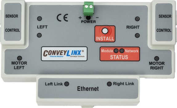
ConveyLinx-ERSC Family
ZPA Input Assembly |
ConveyLinx ERSC ✅ | ConveyLinx-Ai 24V ❌ | ConveyLinx-Ai 48V ❌ |
 |
 |
 |
|
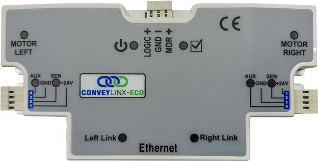
| ConveyLinx-ECO ❌ | ZPA Mode ✅ | PLC I/O Mode ❌ | |
 |
 |
 |
| Register Name | Internal Address | Assembled PLC Address | Description | ||
| Local Status Upstream Zone Forward Direction |
4:0116 | M: 4:1500 (Lo) E: I.Data [0] (Lo) P: Byte 1 |
Unsigned Value of Byte | ||
| Local Status Upstream Zone Reverse Direction |
4:0116 | M: 4:1500 (Hi) E: I.Data [0] (Hi) P: Byte 0 |
0×01 = | Zone Sensor clear and motor stopped | |
| 0×03 = | Zone sensor clear, motor running, accepting from upstream | ||||
| Local Status Downstream Zone Forward Direction |
4:0196 | M: 4:1501 (Lo) E: I.Data [1] (Lo) P: Byte 3 |
0×04 = | Zone sensor blocked, motor running, discharging to downstream | |
| 0×05 = | Zone sensor blocked and motor stopped | ||||
| Local Status Downstream Zone Reverse Direction |
4:0196 | M: 4:1501 (Hi) E: I.Data [1] (Hi) P: Byte 2 |
0×06 = | Busy (state when ConveyStop active) | |
| Arrival Count Local Upstream Zone |
4:0106 | M: 4:1502 E: I.Data [2] P: Byte 4 (Hi) P: Byte 5 (Lo) |
Unsigned Integer Value | ||
| ● | Increments by 1 each time a carton departs in the Upstream zone | ||||
| ● | Value rolls over from 65,535 back to 0 | ||||
| Departure Count Local Upstream Zone |
4:0107 | M: 4:1503 E: I.Data [3] P: Byte 6 (Hi) P: Byte 7 (Lo) |
Unsigned Integer Value | ||
| ● | Increments by 1 each time a carton departs in the Upstream zone | ||||
| ● | Value rolls over from 65,535 back to 0 | ||||
| Arrival Count Local Upstream Zone |
4:0186 | M: 4:1504 E: I.Data [4] P: Byte 8 (Hi) P: Byte 9 (Lo) |
Unsigned Integer Value | ||
| ● | Increments by 1 each time a carton arrives in the Downstream zone | ||||
| ● | Value rolls over from 65,535 back to 0 | ||||
| Departure Count Local Downstream Zone |
4:0187 | M: 4:1505 E: I.Data [5] P: Byte 10 (Hi) P: Byte 11 (Lo) |
Unsigned Integer Value | ||
| ● | Increments by 1 each time a carton departs in the Downstream zone | ||||
| ● | Value rolls over from 65,535 back to 0 | ||||
| Module Status Word 1 |
4:0088 | M: 4:1506 E: I.Data [6] P: Byte 12 (Hi) P: Byte 13 (Lo) |
Bitwise Value | ||
| bit 00 = | Module Reset Flag | ||||
| bit 01 = | Reserved | ||||
| bit 02 = | Input Power Over Voltage >30V | ||||
| bit 03 = | Left Motor Error Active | ||||
| bit 04 = | Ethernet Connection NOT OK | ||||
| bit 05 = | Upstream Jam Error | ||||
| bit 06 = | Left Sensor Error | ||||
| bit 07 = | Input Power Low Voltage <18V | ||||
| bit 08 = | Left Motor Overheat >105°C | ||||
| bit 09 = | Left Motor Over Current | ||||
| bit 10 = | Left Motor Short Circuit | ||||
| bit 11 = | Left Motor NOT Connected | ||||
| bit 12 = | Left Motor Overload >20 seconds stalled | ||||
| bit 13 = | Left Motor Stalled < 10% selected speed | ||||
| bit 14 = | Left Motor Hall Sensor Error | ||||
| bit 15 = | Left Motor Not Used | ||||
| Module Status Word 2 |
4:0089 | M: 4:1507 E: I.Data [7] P: Byte 14 (Hi) P: Byte 15 (Lo) |
Bitwise Value | ||
| bit 00 = | Reserved | ||||
| bit 01 = | Reserved | ||||
| bit 02 = | Input Power Over Voltage >30V | ||||
| bit 03 = | Right Motor Error Active | ||||
| bit 04 = | Reserved | ||||
| bit 05 = | Downstream Jam Error | ||||
| bit 06 = | Right Sensor Error | ||||
| bit 07 = | Input Power Low Voltage <18V | ||||
| bit 08 = | Right Motor Overheat >105°C | ||||
| bit 09 = | Right Motor Over Current | ||||
| bit 10 = | Right Motor Short Circuit | ||||
| bit 11 = | Right Motor NOT Connected | ||||
| bit 12 = | Right Motor Overload >20 seconds stalled | ||||
| bit 13 = | Right Motor Stalled < 10% selected speed | ||||
| bit 14 = | Right Motor Hall Sensor Error | ||||
| bit 15 = | Right Motor Not Used | ||||
| Current Upstream Zone Tracking Word 1 |
4:0119 | M: 4:1508 E: I.Data [8] P: Byte 16 (Hi) P: Byte 17 (Lo) |
Integer Value | ||
| When Carton is accumulated in UPSTREAM zone: | |||||
| Value = Tracking data word #1 (16-bit integer) for the Carton currently accumulated and stopped in the module’s Upstream zone | |||||
| Current Upstream Zone Tracking Word 1 |
4:0120 | M: 4:1509 E: I.Data [9] P: Byte 18 (Hi) P: Byte 19 (Lo) |
Integer Value | ||
| When Carton is accumulated in UPSTREAM zone: | |||||
| Value = Tracking data word #2 (16-bit integer) for the Carton currently accumulated and stopped in the module’s Upstream zone | |||||
| Current Downstream Zone Tracking Word 1 |
4:0199 | M: 4:1510 E: I.Data [10] P: Byte 20 (Hi) P: Byte 21 (Lo) |
Integer Value | ||
| When Carton is accumulated in DOWNSTREAM zone: | |||||
| Value = Tracking data word #1 (16-bit integer) for the Carton currently accumulated and stopped in the module’s Downstream zone | |||||
| Current Downstream Zone Tracking Word 2 |
4:0200 | M: 4:1511 E: I.Data [11] P: Byte 22 (Hi) P: Byte 23 (Lo) |
Integer Value | ||
| When Carton is accumulated in DOWNSTREAM zone: | |||||
| Value = Tracking data word #2 (16-bit integer) for the Carton currently accumulated and stopped in the module’s Downstream zone | |||||
| Current Release Count Upstream Zone |
4:0105 | M: 4:1512 E: I.Data [12] P: Byte 24 (Hi) P: Byte 25 (Lo) |
Integer Value | ||
| Copy of the current value in the Release Upstream output register which can be used by PLC logic to confirm release count prior to writing new data to the Release Upstream output register | |||||
| Current Release Count Downstream Zone |
4:0185 | M: 4:1513 E: I.Data [13] P: Byte 26 (Hi) P: Byte 27 (Lo) |
Integer Value | ||
| Copy of the current value in the Release Downstream output register which can be used by PLC logic to confirm release count prior to writing new data to the Release Downstream output register | |||||
| Get Tracking Forward Direction Word 1 |
4:0201 | M: 4:1514 E: I.Data [14] P: Byte 28 (Hi) P: Byte 29 (Lo) |
Integer Value | ||
| When discharging to Non-ConveyLinx controlled conveyor: | |||||
| Value = Tracking data word #1 (16-bit integer) for the Carton that has just discharged from the local downstream zone when local conveyor is operating in default or “forward” direction | |||||
| Get Tracking Forward Direction Word 2 |
4:0202 | M: 4:1515 E: I.Data [15] P: Byte 30 (Hi) P: Byte 31 (Lo) |
Integer Value | ||
| When discharging to Non-ConveyLinx controlled conveyor: | |||||
| Value = Tracking data word #2 (16-bit integer) for the Carton that has just discharged from the local downstream zone when local conveyor is operating in default or “forward” direction | |||||
| Get Tracking Reverse Direction Word 1 |
4:0121 | M: 4:1516 E: I.Data [16] P: Byte 32 (Hi) P: Byte 33 (Lo) |
Integer Value | ||
| When discharging to Non-ConveyLinx controlled conveyor: | |||||
| Value = Tracking data word #1 (16-bit integer) for the Carton that has just discharged from the local downstream zone when local conveyor is operating in opposite of default or “reverse” direction | |||||
| Get Tracking Reverse Direction Word 2 |
4:0122 | M: 4:1517 E: I.Data [17] P: Byte 34 (Hi) P: Byte 35 (Lo) |
Integer Value | ||
| When discharging to Non-ConveyLinx controlled conveyor: | |||||
| Value = Tracking data word #2 (16-bit integer) for the Carton that has just discharged from the local downstream zone when local conveyor is operating in opposite of default or “reverse” direction | |||||
| Sensor & Control Port Inputs | 4:0035 | M: 4:1518 E: I.Data [18] P: Byte 36 (Hi) P: Byte 37 (Lo) |
Bitwise Value | ||
| bit 00 = | Left Sensor Port – Pin 3 | ||||
| bit 01 = | Left Control Port – Pin 3 | ||||
| bit 02 = | Right Sensor Port – Pin 3 | ||||
| bit 03 = | Right Control Port – Pin 3 | ||||
| bit 04 = | Left Sensor Port – Pin 4 | ||||
| bit 05 = | Left Control Port – Pin 4 | ||||
| bit 06 = | Right Sensor Port – Pin 4 | ||||
| bit 07 = | Right Control Port – Pin 4 | ||||
| bit 15 = | 2 sec ON / 2 sec OFF heartbeat | ||||
| All other bits reserved | |||||
| Reserved | N/A | M: 4:1519 E: I.Data [19] P: Byte 38 (Hi) P: Byte 39 (Lo) |
Integer Value | ||
| Used for Reset Protection connection See topic Assemblies with Reset Protection for details |
|||||
| ConveyStop Status | 4:0019 | M: 4:1520 E: I.Data [20] P: Byte 40 (Hi) P: Byte 41 (Lo) |
Bitwise Value | ||
| Bit 00 = | Reserved | ||||
| Bit 01 = | Reserved | ||||
| Bit 02 = | Reserved | ||||
| Bit 03 = | Reserved | ||||
| Bit 04 = | Reserved | ||||
| Bit 05 = | Stop Active on another module in Stop Group | ||||
| Bit 06 = | Stop Active due to lost communication connection | ||||
| Bit 07 = | Stop Active due to lost PLC connection | ||||
| Bit 08 = | Stop active on Left Control Port | ||||
| Bit 09 = | Stop active on Right Control Port | ||||
| Bit 10 = | Stop Active due to lost PLC connection | ||||
| Bit 11 = | Reserved | ||||
| Bit 12 = | Reserved | ||||
| Bit 13 = | Reserved | ||||
| Bit 14 = | Reserved | ||||
| Bit 15 = | Reserved | ||||