
PLC Developers Guide / PLC I/O Mode Control / PLC Inputs for PLC I/O Mode /
Input Status |
ConveyLinx ERSC ✅ | ConveyLinx-Ai 24V ✅ | ConveyLinx-Ai 48V ✅ |
 |
 |
 |
|
| ConveyLinx-ECO ✅ | ZPA Mode ❌ | PLC I/O Mode ✅ | |
 |
 |
 |
| Register Name | Internal Address | Assembled PLC Address | Description | ||
| Sensor Detect | 4:0036 | M: 4:1702 E: I.Data [2] P: Byte 4 (Hi) P: Byte 5 (Lo) |
Bitwise Value | ||
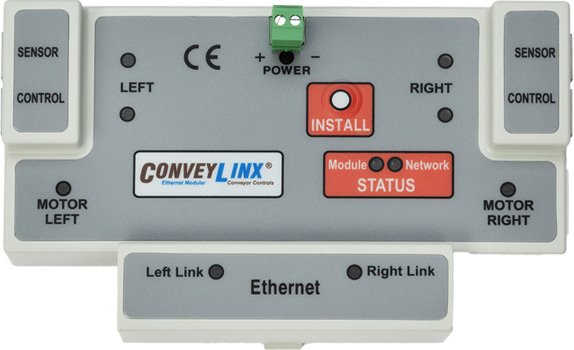
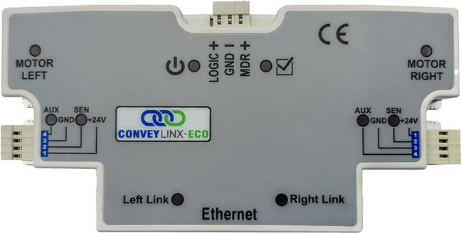
| Bit 00 = | Device is connected to Right Sensor Port | ||||
| Bit 01 = | Device is connected to Left Sensor Port | ||||
| Bit 02 – Bit 15 = Reserved | |||||
| Motor Voltage | 4:0024 | M: 4:1703 E: I.Data [3] P: Byte 6 (Hi) P: Byte 7 (Lo) |
Integer Value | ||
| 1 Module Input Voltage Value in mV | |||||
| Range: 0 to 35000 | |||||
| Example: 23500 = 23.5V | |||||
1 For 48V ConveyLinx Modules the range is up to 50000 mV (50V). Please note that if your PLC Assembly Data Registers are formatted as a Signed Integer, the largest positive 16 bit number visible in your register is 32767 (32.767 V). If you view this register as a Signed Integer, then 48000 (48V) will display as -17536. Please make sure you perform the proper data type functions on the Module Voltage register so that you are viewing and operating on an Unsigned Integer. If your PLC does not support an unsigned 16-bit Integer data type, the you can perform a bitwise distribution into a 32-bit signed data type to properly display the higher voltage values.