PLC Developers Guide / PLC I/O Mode Control / PLC Outputs for PLC I/O Mode / Motor & Sensor Port Digital Output /
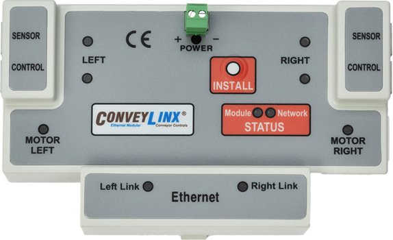
ConveyLinx-Ai Family
Motor and Port Digital Outputs |
ConveyLinx ERSC ❌ | ConveyLinx-Ai 24V ✅ | ConveyLinx-Ai 48V ✅ |
 |
 |
 |
|
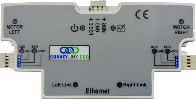
| ConveyLinx-ECO ❌ | ZPA Mode ❌ | PLC I/O Mode ✅ | |
 |
 |
 |
| Register Name | Internal Address | Assembled PLC Address | Description | ||
| Set Digital Control Left Motor Port |
4:0060 | M: 4:1801 E: O.Data [1] P: Byte 2 (Hi) P: Byte 3 (Lo) |
Bitwise Value | ||
| Bit 00 = | Reserved | ||||
| Bit 01 = | Energize Left Motor Port Pin 4 | ||||
| Bit 02 = | Energize Left Motor Port Pin 3 | ||||
| Bit 03 = | Reserved | ||||
| Bit 04 = | Reserved | ||||
| Bit 05 = | Reserved | ||||
| Bit 06 = | Reserved | ||||
| Bit 07 = | Reserved | ||||
| Bit 08 = | Reserved | ||||
| Bit 09 = | Reserved | ||||
| Bit 10 = | Reserved | ||||
| Bit 11 = | Reserved | ||||
| Bit 12 = | Reserved | ||||
| Bit 13 = | Reserved | ||||
| Bit 14 = | Reserved | ||||
| Bit 15 = | Digital Output Mode Enable | ||||
| 0 = Use Left Motor Port for Motor Control | |||||
| 1 = Use Left Motor Port as Digital Outputs | |||||
| Set Digital Control Right Motor Port |
4:0084 | M: 4:1802 E: O.Data [2] P: Byte 4 (Hi) P: Byte 5 (Lo) |
Bitwise Value | ||
| Bit 00 = | Reserved | ||||
| Bit 01 = | Energize Right Motor Port Pin 2 | ||||
| Bit 02 = | Energize Right Motor Port Pin 3 | ||||
| Bit 03 = | Reserved | ||||
| Bit 04 = | Reserved | ||||
| Bit 05 = | Reserved | ||||
| Bit 06 = | Reserved | ||||
| Bit 07 = | Reserved | ||||
| Bit 08 = | Reserved | ||||
| Bit 09 = | Reserved | ||||
| Bit 10 = | Reserved | ||||
| Bit 11 = | Reserved | ||||
| Bit 12 = | Reserved | ||||
| Bit 13 = | Reserved | ||||
| Bit 14 = | Reserved | ||||
| Bit 15 = | Digital Output Mode Enable | ||||
| 0 = Use Right Motor Port for Motor Control | |||||
| 1 = Use Right Motor Port as Digital Outputs | |||||
| Sensor Port Digital Output Control | 4:0037 | M: 4:1803 E: O.Data [3] P: Byte 6 (Hi) P: Byte 7 (Lo) |
Bitwise Value | ||
| Bit 00 = | 1 = Left Pin 2 ON / 0 = Left Pin 2 OFF | ||||
| Bit 01 = | 1 = Right Pin 2 ON / 0 = Right Pin 2 OFF | ||||
| Bit 02 = | Reserved | ||||
| Bit 03 = | Reserved | ||||
| Bit 04 = | Reserved | ||||
| Bit 05 = | 1 = Enable Left Pin 2 as Output / 0 = Enable Left Pin 2 as Input | ||||
| Bit 06 = | 1 = Enable Right Pin 2 as Output / 0 = Enable Right Pin 2 as Input | ||||
| Bit 07 = | Reserved | ||||
| Bit 08 = | Reserved | ||||
| Bit 09 = | Reserved | ||||
| Bit 10 = | Reserved | ||||
| Bit 11 = | Reserved | ||||
| Bit 12 = | Reserved | ||||
| Bit 13 = | Reserved | ||||
| Bit 14 = | Reserved | ||||
| Bit 15 = | Reserved | ||||


