| Register Name / Module Address | Assembled Address for PLC | Description |
|---|---|---|
| Left Motor Current 4:0055 |
M: 4:1704 E: I.Data [4] P: Byte 8 (Hi) Byte 9 (Lo) |
Integer Value in mA for the current the motor is drawing Example: 1900 = 1.9 Amps |
| Left Motor Frequency 4:0056 |
M: 4:1705 E: I.Data [5] P: Byte 10 (Hi) Byte 11 (Lo) |
Integer value in Hz for the electrical frequency the motor is running Example: 300 = 300 Hz |
| Left Motor Temperature 4:0057 |
M: 4:1706 E: I.Data [6] P: Byte 12 (Hi) Byte 13 (Lo) |
High Byte / Low Byte of temperatures in °C High Byte = Calculated motor temperature Low Byte = Temperature reading from the on board sensor |
| Left Motor Status 4:0058 |
M: 4:1707 E: O.Data [7] P: Byte 14 (Hi) Byte 15 (Lo) |
Bitwise Value – Read Only: bit 0 = Motor Rotation Status bit 1 = Motor Rotation Status bit 2 = Port in Digital Mode bit 3 = Reserved bit 4 = Reserved bit 5 = Board Overheat bit 6 = Over-voltage bit 7 = Low Voltage bit 8 = Over-heated bit 9 = Over-current bit 10 = Short Circuit bit 11 = Motor Not Connected bit 12 = Overloaded bit 13 = Stalled bit 14 = Sensor Error bit 15 = Motor Not Used |
| Left Motor Real Speed 4:0507 |
M: 4:1723 E: O.Data [23] P: Byte 46 (Hi) Byte 47 (Lo) |
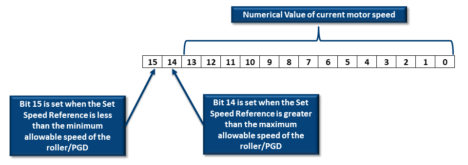
Motor Speed and Speed Status bit 00 thru bit 13 = Numerical value or current speed * For MDR value is in mm/sec * For PGD value is in RPM x 10 bit 14: 1 = Set Speed is above motor’s maximum speed capability bit 15: 1 = Set Speed is below motor’s minimum speed capability |
Motor Rotation Status
Bits 0 and 1 are used in combination to provide 4 possible states. The following chart defines the bit values for these states:
| Bit 1 | Bit 0 | Description |
|---|---|---|
| 0 | 0 | Motor not running, Normal or Servo Braking Mode applied |
| 0 | 1 | Motor running in CCW Direction |
| 1 | 0 | Motor running in CW Direction |
| 1 | 1 | Motor not running and Free Braking Mode applied |
Motor Frequency
This contains the current value of the electrical frequency of the motor if it is running. For Senergy motors, electrical frequency divided by 5 = mechanical frequency. The mechanical frequency is the number of motor rotations per second. You can use this value along with the mechanical gear ratio of the gearbox to calculate the actual running motor RPM. Please consult your Pulseroller catalog for the gear ratio value for the particular part number you are using.
Motor Real Speed
The Ai motor technology encodes the specific motor data into a memory chip inside the motor. This data is read by the ConveyLinx-Ai Family Module. Included in this data are the mechanical characteristics for the motor including the minimum and maximum speed settings. You can enter values in the speed reference registers that are outside the allowable range for the connected motor. If you enter a value greater than the maximum; the speed will be set to the maximum. If you enter a value lower than the minimum, the speed will be set to the minimum.
For the Motor Real Speed input registers, you can know if the value entered in the Speed Reference register is outside the allowable range by monitoring bits 14 and 15 of these registers.

An Example
For example, let’s say we have an MDR whose maximum speed is 1.34 m/s. At this speed, the value in the Real Speed input register will show a decimal value very close or equal to 1340 (which is the speed in mm/s).

If we enter a value of 2.0 m/s for the speed reference (value of 2000 in Speed Reference register) and then run the motor, in the Real Speed input register for that motor you will see a decimal value very close or equal to 17724. Analyzing this value at the bit level, you will see that bit 14 is set indicating that the Speed Reference value is above the maximum value.

If you strip off bit 14 from this value, the remaining decimal value (i.e. the binary value of bits 0 thru 13) will be very close or equal to 1340; which is the maximum speed allowed for the MDR. Similarly, if the Speed Reference value entered is below the minimum value, bit 15 will be set in the motor’s Real Speed register. Stripping out bit 15, the binary value of bits 0 thru 13 will indicate a value very close or equal to the motor’s minimum allowed speed.


