
The Auxiliary I/O Board’s inputs are generic and do not require any configuration. Analog Inputs and Binary Inputs are defined by their associated numbers.
- Binary Input #1 through Binary Input #4
- Analog Input #1 through Analog Input #4
These will reside on the Auxiliary I/O Board (A4) with its dip-switch configured for Auxiliary I/O Board #1.
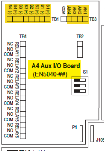
Each relay has a dedicated configuration for:
- alarm condition or status point mapping
- latching or non-latching
- time delay
Auxiliary I/O Board Relays can be mapped to indicate the state of any ATevo alarm or status point. Each relay can be independently configured to latch when the alarm or status point associated with the relay becomes active. Once latched, the relay must be cleared manually by initiating the RESET LATCHED RELAY feature (see Section 7.6). All relays have a time delay configuration. The relay will not change to active state until the associated alarm or status point has changed to active state and remains in active state for the configured time delay.