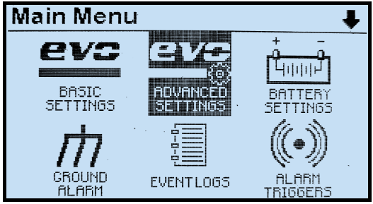
Press ‘MENU’ to access the Main Menu. The first six (6) menu selection icons appear. Use the UP, DOWN, LEFT, or RIGHT arrow buttons to navigate. Icons appear in inverse video when selected.
The top of the screen indicates the Main Menu is being displayed and to the far right of ‘Main Menu’ an up and/or down arrow icon is displayed. The arrow icon(s) indicate that more menu selection icons are available if you continue to navigate in the direction of the arrow.
If a down arrow navigation icon is displayed, and any of the menu icons on the bottom are selected, pressing DOWN again will display the next three menu icons. Pressing the EDIT/ENTER button will activate the selected feature or function. Pressing the ESC button will return back one (1) menu level.
If the Main Menu is being displayed and the ESC button is pressed, the display will return to the HOME screen. If you have selected and entered the SYSTEM SETTINGS mode, pressing the ESC button while in the SYSTEM SETTINGS screen will return to the Main Menu. Pressing ESC again will return to the HOME screen.
The headings below describe the function of all of the buttons in the Main Menu:
6.1.1 Basic Settings Icon
| |
Opens Basic Set Points and Alarms screens beginning with the first parameter. These are the legacy AT30 settings. Refer to Section 4.2 for details.
Selecting this icon is equivalent to pressing EDIT/ENTER from the HOME screen – the direct path to Basic Set Points and Alarms screens, a feature that ensures backward compatibility with legacy AT30 Series battery chargers. |
6.1.2 Advanced Settings Icon
| |
Opens configurable options for Advanced Settings. See Section 4.3 for instructions on advanced setting configurations. |
6.1.3 Battery Settings Icon
| |
Opens configurable options for Battery Settings. Refer to Section 4.11 for instructions. |
6.1.4 Ground Alarm Icon
| |
Opens configurable options for Ground Fault Alarm Settings. Refer to Section 4.10 for instructions. |
6.1.5. Events Log Icon
| |
Opens a list of Event Log functions. The user can view and clear logged events and copy logs to SD memory card. See Section 9 for instructions. |
6.1.6 Alarm Triggers Icon
| |
Used to exclude alarms from the Common Alarm activation list. By default, all alarms, when active, will annunciate the Common Alarm. See Section 4.6 for instructions. |
6.1.7 Relays Icon
| |
Shows relay configuration and control options. Use it to configure relays and reset or clear any latched alarm relays. To change a relay configuration, execute the ‘Relay configuration’ command then select the relay you wish to configure.
Refer to the following sections for details on:
|
6.1.8 Aux Inputs Icon
| |
Used to configure Binary Inputs and Analog Inputs for up to four (4) Auxiliary I/O Boards. Each board may have up to four (4) generic Binary Inputs and four (4) generic Analog Inputs. See Section 12.5 for Binary Inputs, and Section 12.6 for Analog. |
6.1.9 Testing Icon
| |
Displays the Battery Open Test configuration and controls. See Section 7.7 for instructions on how to start, schedule, and set up parameters for the Battery Open Test. |
6.1.10 Communication Icon
| |
Used to configure optional communications ports. ATevo supports three serial communications ports and one Ethernet port. The menu displays all ports, and whether or not they are assigned and configured. Two (2) of the serial ports support DNP3 and Modbus communications for SCADA applications. Refer to the supplementary ATevo Communications Manual for port configuration instructions. |
6.1.11 Save|Reset Configuration Icon
| |
Permits a system backup or restore using an optional SD memory card. All configuration set points, alarm thresholds, and communications settings can be stored on and retrieved from SD memory card. See Section 6.5 for instructions. |
6.1.12 Security Icon
| |
Opens a list of ATevo password and login functions. See Section 6.4 for instructions. |
System Settings Icon
| |
Opens configurable options for System Settings such as time, date, and display backlight intensity. See Section 4.4 for instructions. |
System Information Icon
| |
Allows you to scroll through a screen of system information, including:
- Vdc/Adc (charger output)
- Firmware version
- Display version
- PGA version
- AUX versions (4)
- Time since last reset
- Charger ID
- MAC
|
Last modified:
27 September 2023