
ATevo is a commercial/industrial product. It is not intended for use at any time in a residential environment or to be powered by low-voltage public mains.
It is the responsibility of the installer to provide ac supply wiring approved for use in the country where installed. When selecting wire sizes, consult the data nameplate decal affixed to ATevo for voltage and current requirements.
Guidelines for Supplying AC Power to ATevo
Follow these steps to supply proper ac power to ATevo:
- Confirm that the ATevo nameplate voltage rating is correct for the ac input supply voltage.
- Use a branch circuit breaker or fused disconnect switch upstream from ATevo. This device should have lockout capabilities so that the ac input supply to ATevo can be deenergized for unit maintenance. A time-delay circuit breaker or slow-blow fuse is recommended.
- Size the branch circuit breaker or fused disconnect switch for ATevo’s maximum ac input current as listed on the data nameplate decal. For a table of ratings, refer to standard (JF5072-03).
- Size the ac input wiring per the National Electric Code (NEC), Canadian Electrical Code, local and site codes for the trip rating of the branch circuit breaker or fused disconnect switch.
- Conduit must be properly grounded, and in compliance with the national wiring rules of the country where installed.
- Do not run external ac input power wiring through the same conduit as external dc wiring.
- Use copper or aluminum conductors only.
- For 120 Vac, connect the neutral leg to input terminal (CB1-L2).
- All site requirements of the facility take precedence over these instructions.
PROCEDURE
- Identify your ATevo enclosure type (Style-5070, Style-5030, Style-163, or Style-198). Refer to the applicable image in the sections below.
- Remove safety shield per Section 2.2.
- Run ac input supply wiring into ATevo, ending at the left side of the I/O panel.
- Connect wires to appropriate locations on AC Input CU-AL compression lugs on left side of I/O panel.
- Using a flat-blade screwdriver, securely tighten lugs for L1, L2, L3, and GROUND connections.
- Check all ac input connections, and reinstall safety shield.
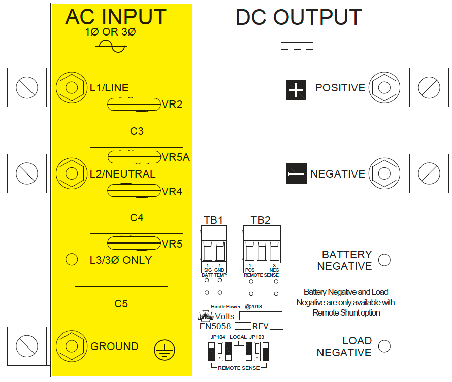
2.4.1 I/O Connections (Style-5070)
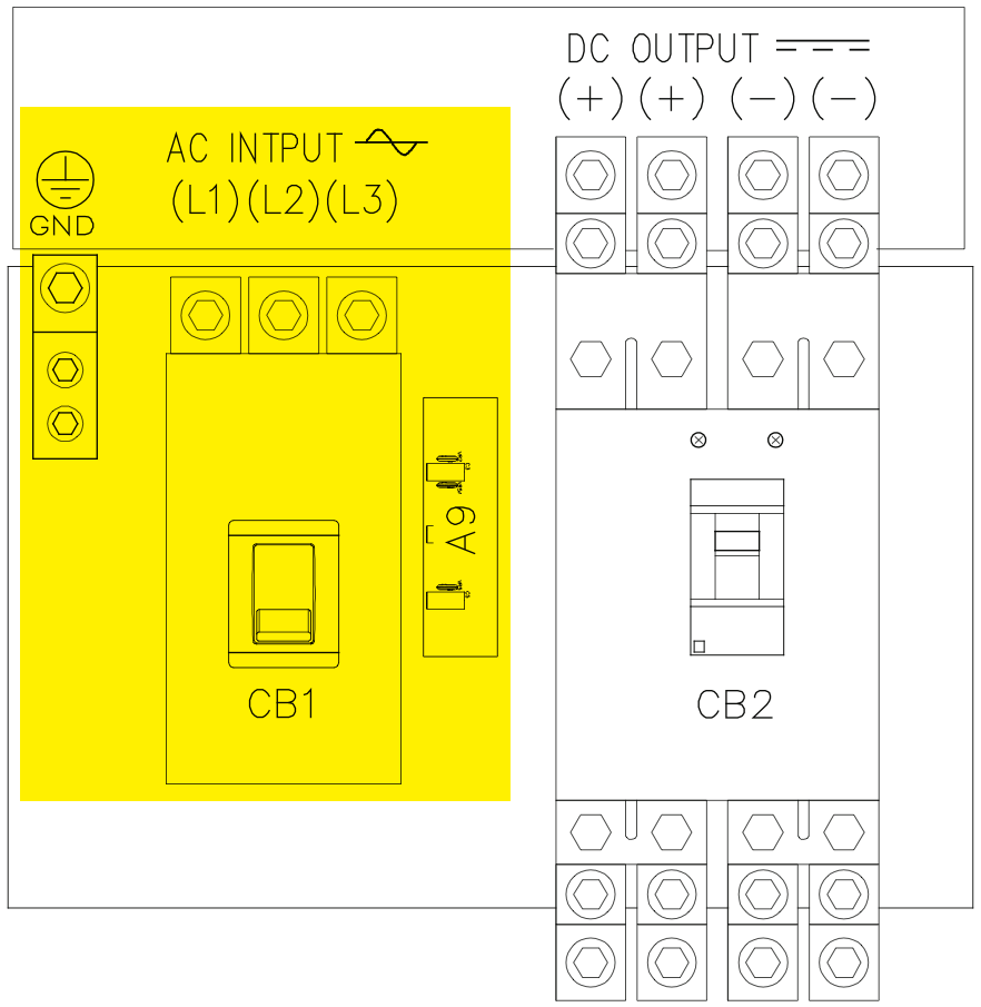
2.4.2 I/O Connections (Style-5030)
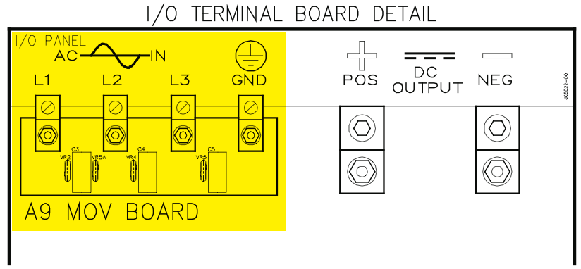
2.4.3 I/O Connections (Style-163/198)
Last modified:
13 September 2023