
ATevo front panel controls and indicators are organized into six (6) major groups or sections.
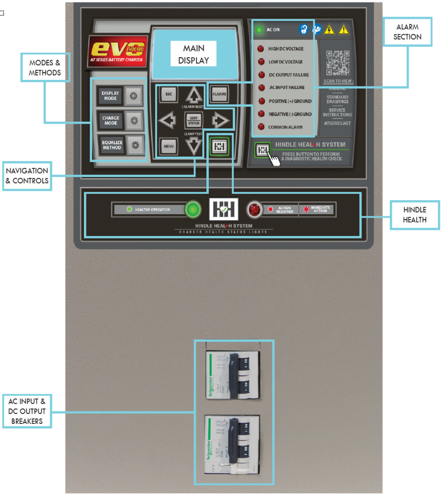
AC INPUT & DC OUTPUT CIRCUIT BREAKERS
Actuator controls for ac input (CB1) and dc output (CB2) circuit breakers are accessible via front panel door cut-outs. See Enclosure Outline Drawings for location and arrangement of internally- mounted circuit breaker protection devices.
- JE5331-00 Style-5070 Enclosure (16-100 Adc)
- JE5337-00 Style-5030 Enclosure (100-300 Adc)
- JE5361-00 Style-163 Enclosure (250-600 Adc)
- JE5351-00 Style-198 Enclosure (600-1000 Adc)
3.1.1 ATevo Main Display
A back-lit Liquid Crystal Display (LCD) shows all charger status and configuration information. The display is discussed in Section 3.2.
3.1.2 Navigation and Control Button Group
This group of buttons (MENU, ESC, EDIT/ENTER, LEFT, RIGHT, UP, and DOWN) is used to navigate ATevo screens and menus. Use of these controls is covered in Section 3.3.
3.1.3 Operation Modes and Methods Button Group
This group of buttons (DISPLAY MODE, CHARGE MODE, and EQUALIZE METHOD) selects the ATevo mode of operation. Use of these controls is covered in Section 5.1.
3.1.4 Alarm Section
The alarm section consists of the discrete alarm indication LEDs, the AC ON indicator (LED), and the ALARMS button. An alarm indicator will light when its associated alarm is activated. The AC ON indicator is lit when ac power is detected by the Main Control Board (A1). The ALARMS button is used to enter screens which display alarm statuses. Alarms and indicators are discussed in Section 7.
3.1.5 Hindle Health System (HHS) Section
The Hindle Health System section consists of the HEALTH BUTTON (HH) and the RED and GREEN health indication LEDs at the bottom of the panel. The Hindle Health System is discussed in Section 8.
3.1.6 AC Input and DC Output Breakers
Molded case circuit breaker protection devices are accessible via actuator cut-outs on the front panel door.
The AC Input Circuit Breaker (CB1) is located on the left. When opened, this device disconnects ATevo internal components from the ac voltage source, except for the breaker terminals (CB1-L1/L2/L3), where the ac input feed is connected.
The DC Output Circuit Breaker (CB2) is to the right. When opened, this device disconnects ATevo output from the dc bus (battery) voltage.
 |
There still may be live dc power connected to some of ATevo’s internal boards (this will include any relays wetted by the battery voltage). |
|---|