
PROBE
The ATevo battery temperature probe (A10) is the same for all battery types (size, chemistry & technology). The same probe (spare p/n EJ5032-01) works with all ATevo models, regardless of dc bus voltage. TempCo accessory kits (p/n EJ5304-##) differ, depending on cable length (25ft, 50ft, 100ft, etc).
INSTALLATION (at ATevo)
- Turn off (open) both ATevo front panel circuit breakers (CB1/CB2).
- De-energize and lock out all ac and dc voltages to ATevo.
- Allow internal voltage potentials to dissipate.
- Open the ATevo front panel door, and remove safety shield.
- Verify no hazardous voltages are present (with a voltmeter).
- Install supplied TempCo cable:
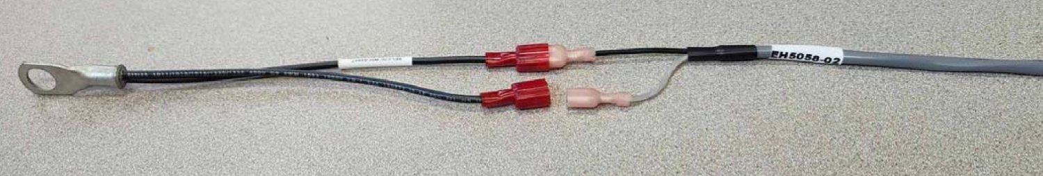
- Identify end of cable with two (2) stripped wires and a quick-connect terminal.
- Insert this end to inside of ATevo enclosure.
- Run cable through conduit that does not contain power wiring.
- Leave 30in / 762mm of cable inside ATevo.
- Coil up excess cable.
- Make sure all wiring conforms to NEC, local, and site requirements.
- Route other end of cable toward the battery.
WIRING (to Style-5070)
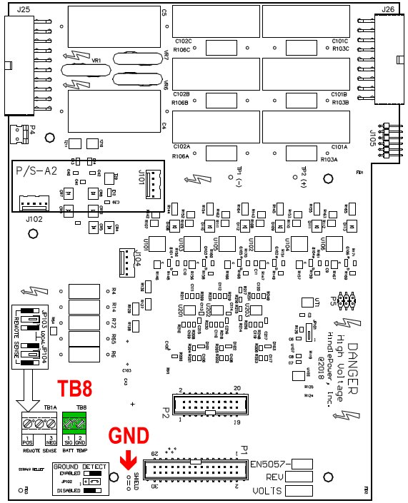
- Identify the ATevo Style-5070 I/O Board (A9), center-mounted at the front enclosure.
- Route TempCo cable to lower end of the I/O Board (A9).
- Locate the 2-position BATT TEMP terminal block (TB8) on the I/O Board.
- Using the stripped ends from the twisted pair, insert one (1) wire into each position of
terminal block (A9-TB8). Connection points are not polarity sensitive. - Tighten screws at the front of terminal block (TB8) onto secure wires.
- Locate the GROUND quick-connect terminal, at the bottom of the I/O Board (A9).
- Attach the quick-connect slip-on lug, at the end of TempCo cable’s shield wire, onto the I/O Board GROUND terminal.
- Fasten the TempCo cable with plastic zip ties.

WIRING (to Style-5030, -163 & -198)
- Identify the ATevo large-style (-5030, -163, -198) Power Board (A2), bracket-mounted to right.
- Route TempCo cable to lower end of the Power Board (A2).
- Locate the 2-position BATT TEMP terminal block (TB8) on the Power Board.
- Using the stripped ends from the twisted pair, insert one (1) wire into each position of
terminal block (A2-TB8). Connection points are not polarity sensitive. - Tighten screws at the front of terminal block (TB8) onto secure wires.
- Locate the SHIELD quick-connect terminal, at the bottom of the Power Board (A2).
- Attach the quick-connect slip-on lug, at the end of TempCo cable’s shield wire, onto the Power Board SHIELD terminal.
- Fasten the TempCo cable with plastic zip ties.
INSTALLATION (at battery)
- At battery location, insert the A10 TempCo probe’s two (2) red quick-connect lugs into the cable’s two (2) pink quick-connect lugs. Polarity of lugged connections is not important.
- Mount connected probe (A10) on, or as close as possible, to the battery.
 – Consult battery manufacturer documentation for mounting restrictions and material compatibilities.
- For most accurate results, the manufacturer of ATevo recommends mounting the TempCo probe to an inter-cell connector, at the middle of the battery string.
! CAUTION – Dangerous voltages exist at the battery.
- Carefully remove hardware on one (1) battery post inter-cell connector.
- Clean and dry the post, connector, and/or mounting hardware if required.
- Place the 3/8in hole ring lug on top of one (1) of the open battery posts (pos[+] or neg[-]).
- Replace the inter-cell connector mounting hardware.
- Tighten hardware, securing TempCo probe in place.
- Replace any protective coverings.
- Refer to image below for example of installed TempCo probe. Other installations may differ depending on available battery mounting provisions.
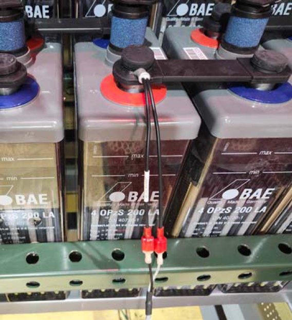
- Coil up and secure excess cable with a nylon zip tie to prevent damage.
- Inspect work at battery, and confirm installation.
RESTART (at ATevo)
- Return to ATevo, check your work, and confirm that:
- All connections are secure.
- Both the TempCo shield and the original ground wire are connected to the EARTH quick-connect terminal (A2-EARTH).
- The twisted-pair wires of the TempCo cable are connected to the 2-position terminal block on the Power Board (A2-TB8).
- Replace safety shield, and close the front panel door.
- Restart ATevo.
10.2.1 Configuring the TempCo Option
ATevo will need to be configured to enable the TempCo probe (A10) and to select the battery type. Refer to Section 4.11 Configuring Battery Settings for both.
Last modified:
2 July 2025