• English
    • Español
ATevo O&SI - 1PH Input Group I (6-25 Adc)
1.1
  • 1.2
  • 1.1
Table of Contents
ATevo O&SI - 1PH Input Group I (6-25 Adc)
  • 1.1
    • ATevo O&SI - 1PH Input Group I (6-25 Adc) — 1.2
    • ATevo O&SI - 1PH Input Group I (6-25 Adc) — 1.1
GrabGrab
GrabGrab
  • 1. Receiving & Mounting
    • 1.1. Storing ATevo
    • 1.2. Receiving ATevo
    • 1.3. Unpacking & Inspecting ATevo
    • 1.4. Reporting Damage or Shortage
    • 1.5. Returning Damaged Equipment
    • 1.6. Moving ATevo
    • 1.7. Mounting ATevo
      • 1.7.1. Wall-Mounting (Style-5054)
      • 1.7.2. Floor-Mounting (Style-5054)
      • 1.7.3. Rack-Mounting (Style-5054)
  • 2. Wiring
    • 2.1. Mechanical Diagram and Component Location
      • 2.1.1. Main Control Board (A1)
      • 2.1.2. Power Board (A2)
      • 2.1.3. Auxiliary I/O Board (A4) – optional
      • 2.1.4. Filter Capacitor Board (A7)
      • 2.1.5. AC MOV Board (A9)
      • 2.1.6. Serial Communications Adapter (A12) – optional
      • 2.1.7. Forced Load Sharing Adapter (A13) – optional
      • 2.1.8. Ethernet Communications Adapter (A22) – optional
      • 2.1.9. Eliminator Capacitor (C2) – optional
      • 2.1.10. AC Input Circuit Breaker (CB1)
      • 2.1.11. DC Output Circuit Breaker (CB2)
      • 2.1.12. Main Filter Inductor (L1)
      • 2.1.13. Secondary Filter Inductor (L2)
      • 2.1.14. Power Isolation Transformer (T1)
    • 2.2. Removing Protective Safety Shield
    • 2.3. ATevo with Selectable Input Voltage – optional
      • 2.3.1. Determining if Multi-Tap Option is Present
      • 2.3.2. Verifying Multi-Tap AC Input Voltage Setting
      • 2.3.3. Modifying Multi-Tap AC Input Voltage Setting
    • 2.4. Making AC Input Connections
    • 2.5. Making DC Output Connections
    • 2.6. Remote Voltage Sense
    • 2.7. Wiring ATevo Common Alarm
    • 2.8. Wiring Relays on Auxiliary I/O Board
    • 2.9. Wiring Temperature Compensation Probe
    • 2.10. Wiring Serial Communications Adapters
    • 2.11. Wiring Ethernet Adapter
  • 3. Controls & Navigation
    • 3.1. Front Panel Controls & Indicators
    • 3.2. Display
      • 3.2.1. Home Screen
      • 3.2.2. Configuration Screens
      • 3.2.3. Status Screens
      • 3.2.4. Hindle Health System Screens
      • 3.2.5. Other Screens
    • 3.3. Main Menu & Navigation
      • 3.3.1. Menu and Arrow Buttons
      • 3.3.2. EDIT/ENTER Button
      • 3.3.3. Navigation Conventions in this Manual
      • 3.3.4. Escape (ESC) Button
  • 4. Startup & Configuration
    • 4.1. Startup
      • 4.1.1. Understanding the Startup Sequence
      • 4.1.2. Factory Settings Tables
      • 4.1.3. Checking Installation
      • 4.1.4. Starting Up
      • 4.1.5. HOME Screen
    • 4.2. Configuring Basic Set Points & Alarms
      • 4.2.1. How to Configure General Parameter Settings
      • 4.2.2. Setting Float Voltage
      • 4.2.3. Setting Equalize Voltage
      • 4.2.4. Setting Equalize Timer
      • 4.2.5. Setting High DC Alarm Voltage
      • 4.2.6. Setting Low DC Alarm Voltage
      • 4.2.7. Setting Current Limit Level
    • 4.3. Configuring Advanced Set Points & Alarms
      • 4.3.1. How to Configure Advanced Settings
      • 4.3.2. Setting High Voltage Shutdown
      • 4.3.3. Setting High Level Detect
      • 4.3.4. Setting Low Voltage Level Detect
      • 4.3.5. Setting Ripple Alarm
    • 4.4. Configuring System Settings
      • 4.4.1. How to Configure System Settings
      • 4.4.2. Setting System Time
      • 4.4.3. Setting System Date
      • 4.4.4. Setting Display Backlight Control
      • 4.4.5. Setting Display Contrast
      • 4.4.6. Setting Display Backlight Intensity
      • 4.4.7. Setting Display Reverse Image Control
    • 4.5. Configuring Relays
      • 4.5.1. Configuring Common Alarm Relay
      • 4.5.2. Configuring Auxiliary I/O Board Relays
    • 4.6. Disabling Alarms in Common Alarm List
    • 4.7. Configuring Serial Communications Adapter
    • 4.8. Configuring Ethernet Adapter
    • 4.9. Enabling/Disabling High Level Detect
    • 4.10. Configuring Ground Alarms
      • 4.10.1. Setting Up Ground Fault Alarm Sensitivity
      • 4.10.2. Setting Up Ground Imbalance Alarm
    • 4.11. Configuring Battery Settings
      • 4.11.1. Selecting Battery Type
      • 4.11.2. Setting End of Discharge (EOD) Alarm
      • 4.11.3. Setting Up the Battery Temperature Probe
  • 5. Basic Operation
    • 5.1. ATevo Operating Modes
      • 5.1.1. Changing Display Mode
      • 5.1.2. Changing Charge Mode
      • 5.1.3. Changing Equalize Method
      • 5.1.4. Lamp Test & Display of Firmware Versions
      • 5.1.5. Resetting Latched Relays (legacy method)
    • 5.2. High Voltage Shutdown
    • 5.3. Low Level Detect
    • 5.4. High Level Detect
    • 5.5. Disabling Ground Detection
  • 6. Advanced Operation
    • 6.1. ATevo Main Menu
    • 6.2. Alarms Button
    • 6.3. Health Button
    • 6.4. Security & Passwords
      • 6.4.1. Three (3) Levels of Password Protection
      • 6.4.2. Access Security Features & Configure Passwords
      • 6.4.3. Setting Passwords
      • 6.4.4. Setting Default Permission
      • 6.4.5. Logging into a Password Authorization Level
      • 6.4.6. Logging Out
    • 6.5. SD Memory Card Features
      • 6.5.1. Installing SD Memory Card
      • 6.5.2. Storing Event Log File to SD Card
      • 6.5.3. Storing/Recalling Settings to/from Memory Card
      • 6.5.4. Upgrading Firmware via Memory Card (v2.6.6 & earlier)
      • 6.5.5. Upgrading Firmware via Memory Card (v2.7.0 onward)
  • 7. Alarms & Indicators
    • 7.1. Legacy AT10.1 Alarms & Indicators
    • 7.2. Common Alarm Indicator & Other Alarm Triggers
    • 7.3. Alarm LED Summary Table
    • 7.4. Viewing Alarms
    • 7.5. Advanced Alarms
    • 7.6. Resetting Latched Alarm Relays
    • 7.7. Battery Open Test
      • 7.7.1. Battery Open Test Settings
      • 7.7.2. Running Battery Open Tests Periodically
      • 7.7.3. Running Battery Open Test Manually
      • 7.7.4. Resetting Battery Open Alarm
    • 7.8. AC Metering – optional
    • 7.9. Battery Discharge Alarm / Meter – optional
  • 8. Hindle Health System
    • 8.1. Hindle Health System – Overview
    • 8.2. Hindle Health System – Components
    • 8.3. Hindle Health System – Screens
    • 8.4. Hindle Health+ – optional
  • 9. Event Logs
    • 9.1. Event Log Types
    • 9.2. Viewing Event Log
    • 9.3. Viewing Hindle Health Log
    • 9.4. Clearing Event Logs
    • 9.5. Copying Event Logs to SD Memory Card
  • 10. Battery Temperature Compensation
    • 10.1. ATevo Battery Temperature Compensation
    • 10.2. Installing the TempCo Option
    • 10.3. Using the TempCo Option
    • 10.4. Temperature Compensation Curves
  • 11. Remote Sense
    • 11.1. ATevo Remote Voltage Sense
    • 11.2. Remote Sense Connection
    • 11.3. Procedure for Wiring Remote Sense
    • 11.4. Configuring Remote Sense Jumpers
    • 11.5. Disabling Remote Sense
    • 11.6. Enabling Remote Sense Compensation
  • 12. Auxiliary Inputs/Outputs
    • 12.1. Auxiliary Input/Output (I/O) Board
      • 12.1.1. Relays
      • 12.1.2. Binary Inputs
      • 12.1.3. Analog Inputs
    • 12.2. Connections to Auxiliary I/O Board
      • 12.2.1. System Connections
      • 12.2.2. Wiring Relay Connections
      • 12.2.3. Wiring Binary Input Connections
      • 12.2.4. Wiring Analog Input Connections
    • 12.3. Hardware Configuration
    • 12.4. Software Configuration for Relays
      • 12.4.1. Auxiliary I/O Board Relay Configuration
      • 12.4.2. Auxiliary I/O Board Relay Alarm Configuration
      • 12.4.3. Auxiliary I/O Board Relay Latch Configuration
      • 12.4.4. Auxiliary I/O Board Relay Time Delay Configuration
      • 12.4.5. Factory Default Alarm Relay Configuration
    • 12.5. Software Configuration for Binary Inputs
      • 12.5.1. Binary Input Configuration
      • 12.5.2. Binary Input Name Assignment
      • 12.5.3. Binary Active State Assignment
      • 12.5.4. Binary Input Alarm Enable
      • 12.5.5. Binary Input Action Assignment
      • 12.5.6. Factory Default Binary Input Configuration
    • 12.6. Software Configuration for Analog Inputs
      • 12.6.1. Analog Input Configuration
      • 12.6.2. Analog Input Name Assignment
      • 12.6.3. Analog Input Primary Unit Assignment
      • 12.6.4. Analog Input Scaling Assignment
      • 12.6.5. Analog Input Alarm and Trigger Assignment
      • 12.6.6. Analog Input Alarm Threshold Assignment
      • 12.6.7. Analog Input Action Assignment
      • 12.6.8. Factory Default Analog Input Configuration
  • 13. Forced Load Sharing
    • 13.1. Forced Load Sharing – Introduction
    • 13.2. Forced Load Sharing – System Requirements
    • 13.3. Forced Load Sharing – Configuration
    • 13.4. Wiring ATevo Chargers for Forced Load Sharing
      • 13.4.1. Configuring ATevo for Forced Load Sharing
    • 13.5. Forced Load Sharing Operation
      • 13.5.1. Requirements to Maintain Forced Load Sharing
      • 13.5.2. Virtual Independent Mode
      • 13.5.3. Forced Load Sharing Alarms
    • 13.6. Temperature Compensation with Forced Load Sharing
    • 13.7. Battery Open Alarm for Forced Load Sharing
    • 13.8. Timed Equalize with Forced Load Sharing
    • 13.9. Auto-Equalize with Forced Load Sharing
    • 13.10. Firmware Updates with Forced Load Sharing
    • 13.11. Troubleshooting Forced Load Sharing ATevos
  • 14. Maintenance
    • 14.1. Performing Routine Maintenance
    • 14.2. Ordering Replacement Parts
    • 14.3. Replacing Defective Components
      • 14.3.1. Removing Safety Shield
      • 14.3.2. Replacing Main Control Board (A1)
      • 14.3.3. Replacing Serial Communications Adapter (A1#)
      • 14.3.4. Replacing Ethernet Adapter (A22)
      • 14.3.5. Replacing Rectifier / Heat Sink Assembly (A6)
      • 14.3.6. Replacing Power Board (A2)
      • 14.3.7. Replacing Auxiliary I/O Board (A4)
      • 14.3.8. Replacing Filter Capacitor Board Assembly (A7)
      • 14.3.9. Replacing Eliminator Filter Capacitor (C2) – optional
      • 14.3.10. Replacing Circuit Breakers (CB1/CB2)
      • 14.3.11. Replacing Power Isolation Transformer (T1)
      • 14.3.12. Replacing Filter Inductors (L1/L2)
      • 14.3.13. Replacing DC Power Supply (P/S-A2)
      • 14.3.14. Replacing MOV Surge Suppressor Board (A9)
  • 15. Appendices & Drawings
    • 15.1. Appendix A – Specifications
    • 15.2. Appendix B – Documentation & Drawings
      • 15.2.1. Manuals & Technical Documents
      • 15.2.2. Complete Standard Drawings Binders
        • 15.2.2.1. Enclosure Outline Drawings
        • 15.2.2.2. Internal Component Layout Drawings
        • 15.2.2.3. Control Panel / PC Board Detail Drawings
        • 15.2.2.4. Electrical Schematics
        • 15.2.2.5. Connection (Wiring) Diagrams
    • 15.3. Appendix C – Document Control Information
  • 16. Firmware v2.7.0 Enhancements
    • 16.1. Alarm Triggers
    • 16.2. Disable Equalize
    • 16.3. Menu Changes
  • 17. Safety Instructions
    • 17.1. Safety Symbols
    • 17.2. Equipment Misuse
    • 17.3. DANGER
    • 17.4. WARNING
    • 17.5. CAUTION
  • 18. Warranty
Download as PDF

15.2.2.5. Connection (Wiring) Diagrams

15.2.2.4. Electrical Schematics
15.3. Appendix C – Document Control Information
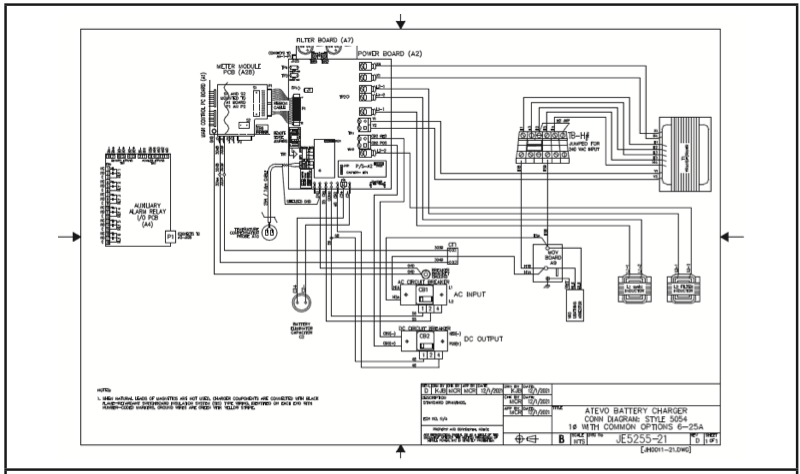
standard (http://www.atseries.net/PDFs/JE5255-01.pdf)
optional (http://www.atseries.net/PDFs/JE5255-21.pdf)
Last modified: 3 August 2023
15.2.2.4. Electrical Schematics
15.3. Appendix C – Document Control Information

Need more help with this?
Don’t hesitate to contact us here.

Thanks for your feedback.
Copyright HindlePower Inc. 2024