
The Auxiliary I/O Board (A4) is an optional component that mounts near the top of the heat sink on the left side of the ATevo . It is equipped with:
- Six (6) relays
- Four (4) generic Binary Inputs
- Four (4) generic Analog Inputs
When supplied, the Auxiliary I/O Board (A4) is electrically connected to and mounts on the Power Board (A2). The Auxiliary I/O Board (A4) links to the Main Control Board (A1), via serial communications, through the ribbon cable connected from the Power Board (A2).
A GREEN communications LED on the Auxiliary I/O Board (A4) is located adjacent to terminal block (A4-TB2). This LED blinks to indicate active communication between the Aux I/O Board and the Main Board.
All relays on the Auxiliary I/O Board (A4) are ‘failsafe’. If communication is lost between the Main Control Board (A1) and the Auxiliary I/O Board (A4), the relays will switch to the alarm state.
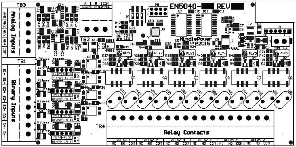
For component details of the Auxiliary I/O Board (A4), refer to standard drawing:
JE5253-21 (Style-5054, up to 25Adc, w/options)
Need more help with this?
Don’t hesitate to contact us here.