ATevo alarms can be divided into two groups: Legacy AT10.1 Alarms (described in Section 7.1) and Advanced Alarms (described below):
Advanced Alarms:
- Do not have dedicated LEDs to indicate when they are active.
- Illuminate the COMMON ALARM LED and activate the common alarm relay
- Appear on the Active Alarm Bar and Active Alarm List.
- Get stored in the event log along with the time and date they occur and clear.
- Will be reported by any installed optional protocol communications board.
- May be configured to activate a discrete relay on optional Auxiliary I/O Boards.
7.5.1 High Voltage Shutdown Alarm
This alarm is activated when ATevo initiates a High Voltage Shutdown, provided that feature has been enabled. See Section 4.3.2 for details. High Voltage Shutdown is initiated by the micro-controller when the dc bus voltage sensed by the Main Control Board (A1) is higher than the High DC Voltage set point for a minimum of thirty (30) seconds. Section 5.2 describes High Voltage Shutdown in detail.
7.5.2 Low Level Detect Alarm
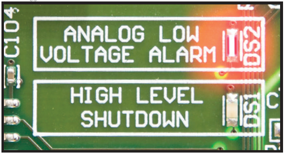
This alarm is activated when the dc bus voltage sensed by the Main Control Board (A1) is lower than the Low Level Detect set point. See Section 4.3.4 for details. The Low Level Detect feature contains dedicated hardware, and operates independent of microprocessor control. The Low Level Detect is a true failsafe feature that activates the common alarm relay in response to a catastrophic failure, such as microprocessor failure. The Low Level Detect hardware will illuminate a dedicated LED located on the Main Control Board (A1) when alarm is active.

7.5.3 End of Discharge (EOD) Alarm
This alarm is activated when the dc bus voltage sensed by the Main Control Board (A1) is lower than the End of Discharge Alarm set point. See Section 4.11.2 for details.
7.5.4 High AC Ripple Alarm
This alarm is activated when the ac ripple voltage measured by the Main Control Board (A1) is higher than the Ripple Voltage Alarm set point. See Section 4.3.5 for details.
7.5.5 Battery Temperature Probe Failure Alarm
This alarm is activated when the Main Control Board (A1) senses an out-of-range value from the battery temperature probe (A10). ATevo will switch to non-temperature compensated mode, adjusting output voltage for 25 °C. Set points for this alarm are not adjustable.
7.5.6 Rectifier Over-Temperature Alarm
The Rectifier Over-Temperature alarm is activated when the Main Control Board (A1) senses that one or more of the SCRs are too hot. Set points for this alarm are not adjustable.
7.5.7 External Feedback Failure Alarm
This alarm is activated when the Main Control Board (A1) senses the (post-filtered) external voltage is out-of-range. The external voltage may be measured at the output breaker or at the battery if the remote sense option is connected. This failure typically indicates a problem with the voltage-sense resistors. Set points for this alarm are not adjustable.
7.5.8 Internal Feedback Failure Alarm
This alarm is activated when the Main Control Board (A1) senses the (pre-filtered) internal voltage is out-of-range. The internal voltage is always measured inside the ATevo, before the dc output filter circuitry. This failure typically indicates a problem with the voltage-sense resistors. Set points for this alarm are not adjustable.
7.5.9 Open DC Breaker Alarm
This alarm is activated when the Main Control Board (A1) senses that the DC Output Circuit Breaker (CB2) is open. The set point for this alarm is not adjustable.
7.5.10 Open AC Breaker Alarm – optional
This alarm is activated when the Main Control Board (A1) senses that AC Input Circuit Breaker (CB1) is open. The set point for this alarm is not adjustable.
7.5.11 DC Power Supply Failure Alarm
This alarm is activated when the Main Control Board (A1) is not sensing power from its internal dc voltage source. ATevo is powered by both ac and dc sources. It uses the ac power source when one is available, but its dc source (P/S-9V) when there is no ac.
ATevo may be operating when this alarm is active, but it may fail when the ac power is removed. Set points for this alarm are not adjustable.
7.5.12 SCR Failure Alarm
This alarm is activated when the Main Control Board (A1) detects that the Rectifier Assembly (A6) is not working. This may indicate a defective SCR or issues with the SCR firing control or driver. Set points are not adjustable.
Need more help with this?
Don’t hesitate to contact us here.


