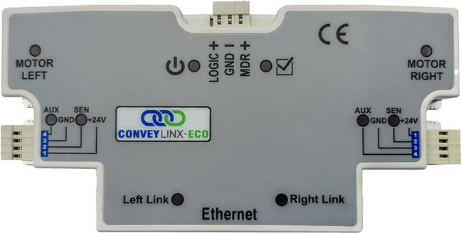
PLC Developers Guide / PLC I/O Mode Control / PLC Inputs for PLC I/O Mode /
Servo Control Status |
ConveyLinx ERSC ✅ | ConveyLinx-Ai 24V ✅ | ConveyLinx-Ai 48V ✅ |
 |
 |
 |
|
| ConveyLinx-ECO ✅ | ZPA Mode ❌ | PLC I/O Mode ✅ | |
 |
 |
 |
| Register Name | Internal Address | Assembled PLC Address | Description | ||
| Servo Position Left Motor |
4:0062 | M: 4:1719 E: I.Data [19] P: Byte 38 (Hi) P: Byte 39 (Lo) |
Signed Integer Value | ||
| Value that indicates the current position of the Left Motor in relation to its “0” position | |||||
| Servo Position Right Motor |
4:0086 | M: 4:1720 E: I.Data [20] P: Byte 40 (Hi) P: Byte 41 (Lo) |
Signed Integer Value | ||
| Value that indicates the current position of the Right Motor in relation to its “0” position | |||||
| Servo Status Left Motor |
4:0011 | M: 4:1721 E: I.Data [21] P: Byte 42 (Hi) P: Byte 43 (Lo) |
Bitwise Value | ||
| Bit 00 = | Servo Status | ||||
| 1 = Last Left Servo Run Command is complete | |||||
| 0 = Left Servo Command in process | |||||
| Bit 01 = | Servo Reset Status | ||||
| Echoes state of Left Motor Servo Cmd Bit 00 | |||||
| Bit 02 = | Servo Command Status | ||||
| Echoes state of Left Motor Servo Cmd Bit 00 | |||||
| Servo Status Right Motor |
4:0016 | M: 4:1722 E: I.Data [22] P: Byte 44 (Hi) P: Byte 45 (Lo) |
Bitwise Value | ||
| Bit 00 = | Servo Status | ||||
| 1 = Last Right Servo Run Command is complete | |||||
| 0 = Right Servo Command in process | |||||
| Bit 01 = | Servo Reset Status | ||||
| Echoes state of Right Motor Servo Cmd Bit 00 | |||||
| Bit 02 = | Servo Command Status | ||||
| Echoes state of Right Motor Servo Cmd Bit 00 | |||||
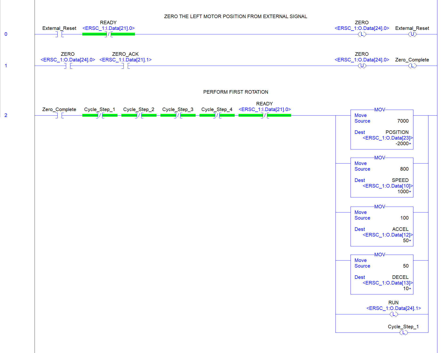
- Servo Control Example
For our example, we want to perform the following cycle using PLC control of the Left MDR on an ConveyLinx Module:
- Establish a zero or home position by external input to the module form a PLC (sensor or operator button)
- Rotate in the CCW direction for 7000 mm at a speed of 0.8 m/s with acceleration ramp of 100 mm and a deceleration ramp of 50 mm
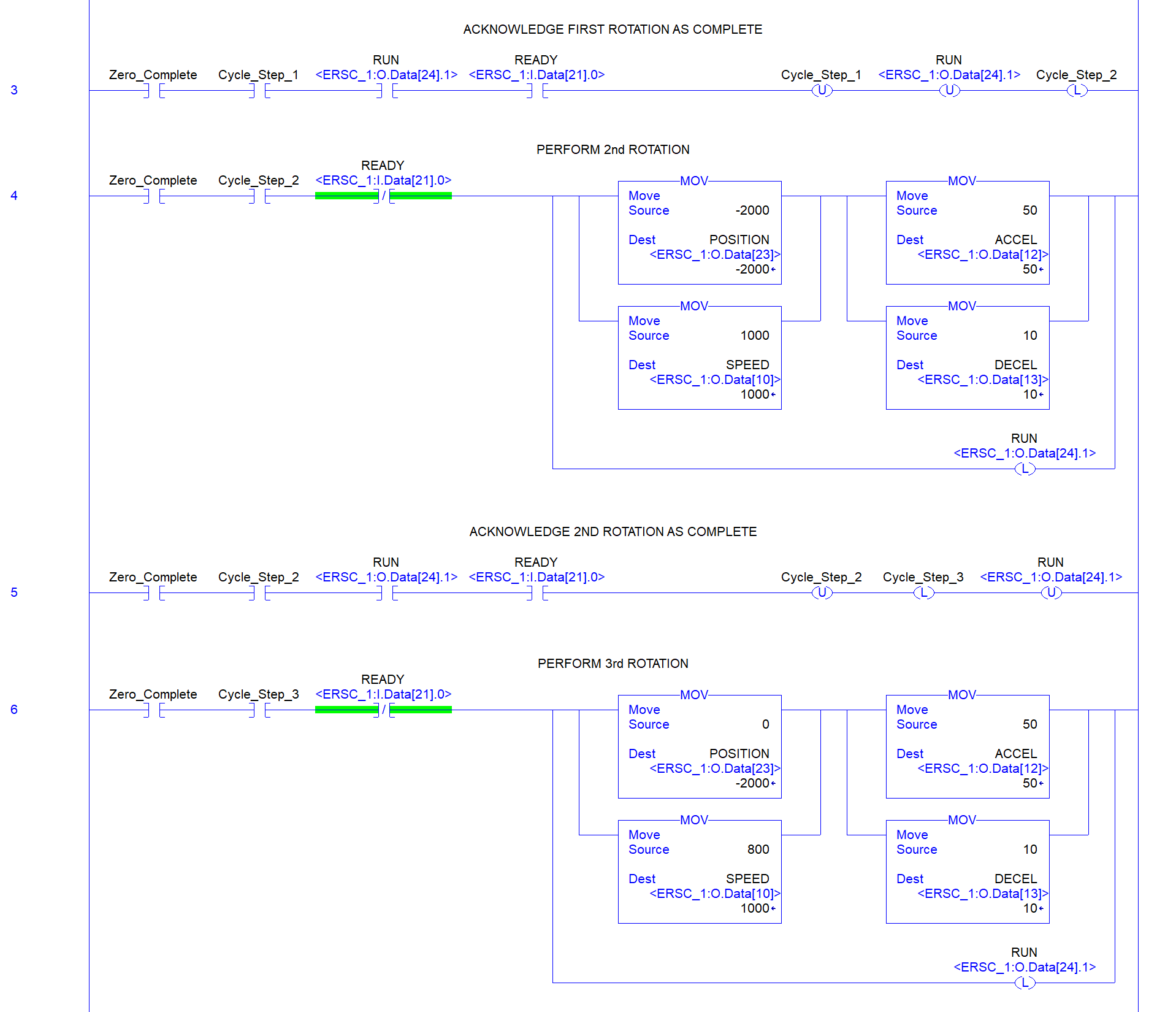
- Rotate the CW direction for 9000 mm at a speed of 1.0 m/s with acceleration ramp of 50 mm and a deceleration ramp of 10 mm.
- Rotate CCW back to the zero or home position at a speed of 0.8 m/s with acceleration ramp of 50 mm and a deceleration ramp of 10 mm.
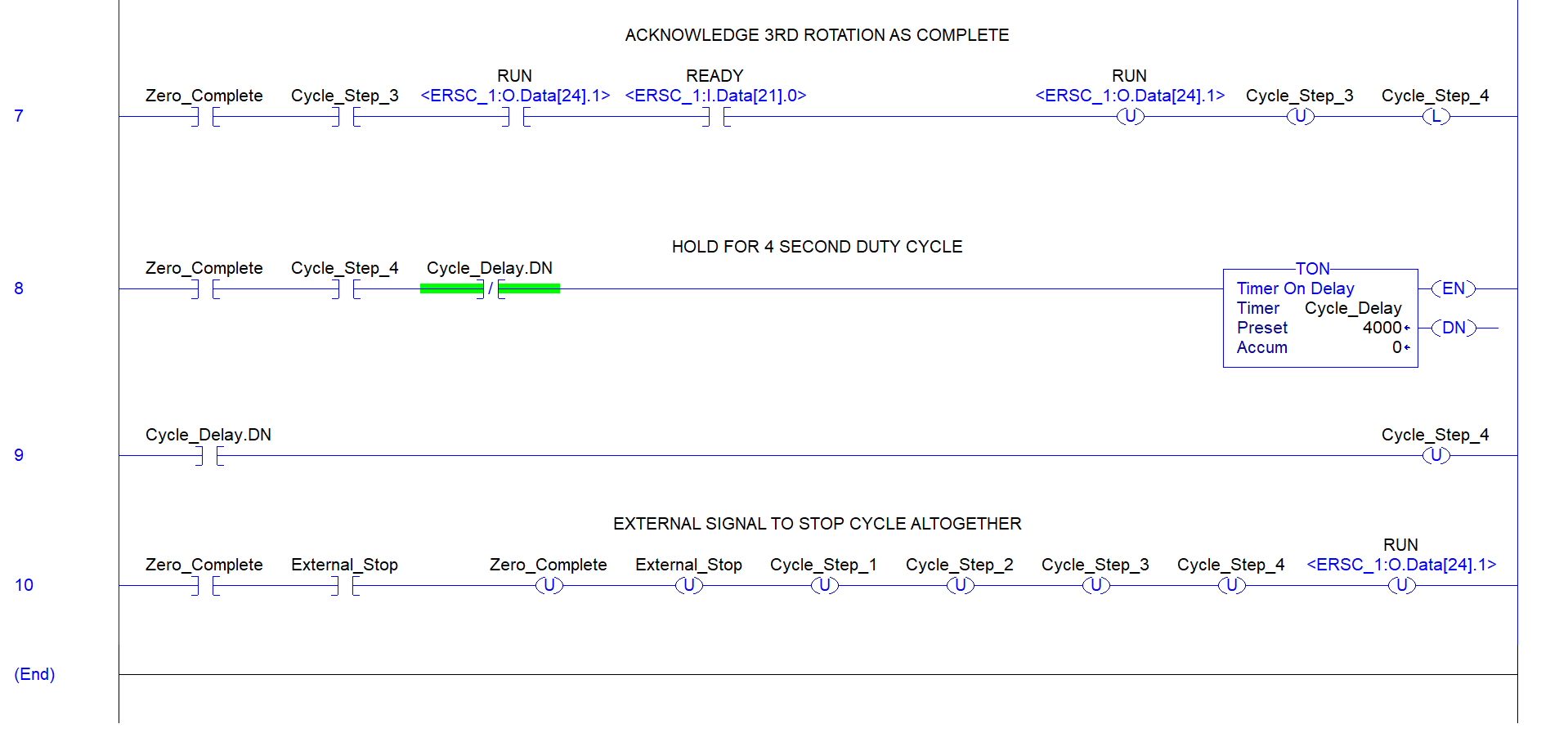
- Wait for a cycle dwell time of 4 seconds and then repeat the rotation cycles
Define PLC Tags
Tag Name Data Type Assembly Register (/bit) ZERO Boolean Left Servo Command Word – bit 0 ZERO_ACK Boolean Left Motor Servo Status – bit 1 RUN Boolean Left Servo Command Word – bit 1 READY Boolean Left Motor Servo Status – bit 0 POSITION Integer Left Servo Command Pulses SPEED Integer Left Motor Speed Reference ACCEL Integer Left Motor Acceleration Ramp DECEL Integer Left Motor Deceleration Ramp Sequence of Operation
Step #1: Upon external signal from sensor or button, set ZERO bit to establish zero or “home” position. When PLC sees that the ZERO_ACK bit is set, then the PLC resets the ZERO bit.
Step #2: To make the first rotation, we need write the speed, ramp values, and distance to rotate to the appropriate registers:
- Write 800 to SPEED
- Write 100 to ACCEL
- Write 50 to DECEL
- Write 7000 to POSITION
Step #3: If READY is reset, then the PLC can set the RUN bit to begin the rotation. When the rotation is complete, the module sets the READY bit. This will be the signal to the PLC to reset the RUN bit. Once the module sees that the RUN bit has been reset, it will reset the READY bit.
Step #4: For the second rotation, we need to write the speed and ramp values to the appropriate registers:
- Write 1000 to SPEED
- Write 50 to ACCEL
- Write 10 to DECEL
Because we want to rotate in the opposite direction, we need to determine the new location based upon the zero or “home” position. In this case, we know we went 7000 mm “forward” and we want to move 9000 mm “backward”. The position we want to end up is 7000-9000 = -2000.
- Write -2000 to POSITION
Step #5: Repeat Step #4
Step #6: For the 3rd rotation, we keep the ramp values from the 2nd rotation, but we need to set the speed and the position to rotate. In this case we want to go to the zero or “home position.
- Write 800 to SPEED
- Write 0 to POSITION
Step #7: Repeat Step #4
PLC Ladder Diagram
![]()
![]()
![]()