• English
    • Japanese
ConveyLinx ERSC Family Complete Guide
5.0
  • 6.0
  • 5.1
  • 5.0
  • 4.9
Table of Contents
ConveyLinx ERSC Family Complete Guide
  • 5.0
    • ConveyLinx ERSC Family Complete Guide — 6.0
    • ConveyLinx ERSC Family Complete Guide — 5.1
    • ConveyLinx ERSC Family Complete Guide — 5.0
    • ConveyLinx ERSC Family Complete Guide — 4.9
GrabGrab
GrabGrab
  • 1. About This Manual
  • 2. Glossary of Terms
  • 3. Getting Started
  • 4. Module Hardware
    • 4.1. Identifying Module Components
    • 4.2. Mounting Dimensions
    • 4.3. Motor Ports
    • 4.4. Sensor & Control Ports
    • 4.5. Ethernet Ports
    • 4.6. Module Internal Fusing
    • 4.7. Over-Voltage Protection
    • 4.8. LED Status Indicators
    • 4.9. Power and Network Connections
    • 4.10. Power Supply Sizing
    • 4.11. Technical Specifications
  • 5. Auto-Configuration
    • 5.1. Linear Conveyor
      • 5.1.1. Device Connections to Modules
      • 5.1.2. Examples that will generate errors
      • 5.1.3. Motor Rotation Definition
    • 5.2. Procedure
    • 5.3. Auto-Configuration Examples
    • 5.4. Expected Results
    • 5.5. What to do if things go wrong
  • 6. Default Settings and Operation
    • 6.1. Singulation Release Mode
    • 6.2. Flex Zone Recognition
    • 6.3. Jam Conditions
      • 6.3.1. Arrival Jam
      • 6.3.2. Sensor Jam
    • 6.4. Hard-Wired Interlocks
      • 6.4.1. Upstream Interlock (Wake Up)
      • 6.4.2. Downstream Interlock (Lane Full)
      • 6.4.3. Local Zone Accumulate
      • 6.4.4. Interlocks with Single Zone Module
      • 6.4.5. Interlock Input versus Local Accumulate Input
      • 6.4.6. Using a Photoeye for Wake-Up
      • 6.4.7. Using a Photoeye for Lane Full
      • 6.4.8. SE Breakout Module
    • 6.5. Automatic Module Replacement
    • 6.6. Reset to Factory Default Settings
  • 7. SE Breakout Module
    • 7.1. Typical Output Connection
    • 7.2. Typical Input Connections
    • 7.3. Input Circuit Blocking Diode Jumpers
    • 7.4. Notes on SE Module Revisions
  • 8. EasyRoll Software
    • 8.1. Installing EasyRoll on your PC
    • 8.2. ConveyLinx Ethernet Definition
    • 8.3. Connecting your PC to ConveyLinx
    • 8.4. Using Discover Function
    • 8.5. Main Screen
      • 8.5.1. Node Navigation
      • 8.5.2. Node Identification
      • 8.5.3. ZPA Upstream/Downstream Zone Settings
        • 8.5.3.1. ZPA Release Mode
          • 8.5.3.1.1. Singulation Release
          • 8.5.3.1.2. Train Release
          • 8.5.3.1.3. GAP Train Release
        • 8.5.3.2. T-Zone Settings
        • 8.5.3.3. ZPA Error and Information
        • 8.5.3.4. Accumulate Control from Main Screen
        • 8.5.3.5. Settings Checkboxes
          • 8.5.3.5.1. Disable Reset Delays
          • 8.5.3.5.2. Disable Sensor Jam Auto Clear
          • 8.5.3.5.3. Disable Arrival Timeout
          • 8.5.3.5.4. Disable Manual Operation
          • 8.5.3.5.5. Dynamic Release
      • 8.5.4. Motor Settings
        • 8.5.4.1. Motor Type
        • 8.5.4.2. Brake Method
        • 8.5.4.3. Speed Control Method
        • 8.5.4.4. Speed
        • 8.5.4.5. Rotation Direction
        • 8.5.4.6. Acceleration/Deceleration
        • 8.5.4.7. Motor Jog and Error Indicators
        • 8.5.4.8. Motor Pulse to Distance Calculation
      • 8.5.5. Diagnostic Window
    • 8.6. Advanced Dialog
      • 8.6.1. Look Ahead and Timing Tab
        • 8.6.1.1. Look Ahead Slowdown Feature
        • 8.6.1.2. Jam Auto Clear Timers
        • 8.6.1.3. Run After Time/Distance
        • 8.6.1.4. Induct Forward Time/Distance
        • 8.6.1.5. Induct Reverse Time/Distance
        • 8.6.1.6. Sensor Debounce
        • 8.6.1.7. Reversing Control in ZPA Mode
      • 8.6.2. Upgrade Tab
      • 8.6.3. Connections Tab
      • 8.6.4. Network Services Tab
        • 8.6.4.1. Discover and IP Address Set
        • 8.6.4.2. Position and DHCP
        • 8.6.4.3. Network Lock Feature
        • 8.6.4.4. Backup and Restore
      • 8.6.5. Special Services Tab
        • 8.6.5.1. Motor Slave Function
      • 8.6.6. Control Ports Tab
        • 8.6.6.1. Control Port Inputs
        • 8.6.6.2. Control Port Outputs
        • 8.6.6.3. Upstream/Downstream Accumulation
        • 8.6.6.4. Lane Full Interface
        • 8.6.6.5. PLC Control of Control Ports
      • 8.6.7. Flex Zone Tab
      • 8.6.8. Sensors Tab
      • 8.6.9. Extensions Tab
  • 9. ConveyMerge
    • 9.1. ConveyMerge Prerequisites and Requirements
    • 9.2. Network Architecture
    • 9.3. Sensor Placement
    • 9.4. Merge Zone Module
    • 9.5. Merging Lines
    • 9.6. Merge Configurations
    • 9.7. Merge Priority
    • 9.8. T-Merge Settings
    • 9.9. Configuring Dynamic Priority Release
    • 9.10. Enabling ConveyMerge from EasyRoll
    • 9.11. Conventional Spur Merge Example
    • 9.12. T-Merge Example
    • 9.13. Merge Line Full Example
  • 10. ConveyStop
    • 10.1. Benefits of ConveyStop
    • 10.2. Using ConveyStop in an Integrated Stop System
    • 10.3. ConveyStop Architecture
    • 10.4. ConveyStop Software
      • 10.4.1. User Accounts
      • 10.4.2. Creating a New Project
      • 10.4.3. Discovering Modules
      • 10.4.4. Creating Stop Groups
      • 10.4.5. Add Stop and Start Buttons
      • 10.4.6. Commit All Button
      • 10.4.7. Status Monitoring
    • 10.5. Issuing a Stop Command
      • 10.5.1. Other Conditions that cause Stop
      • 10.5.2. Indications a Stop is Active
      • 10.5.3. ERSC Functions Affected by Stop Command
      • 10.5.4. CNIP Functions Affected by Stop Command
    • 10.6. ConveyLinx Function at Stop Group Boundaries
    • 10.7. Issuing a Start Command
      • 10.7.1. Indications Start is Active
    • 10.8. Using a PLC with ConveyStop
      • 10.8.1. ConveyStop Status Register
      • 10.8.2. ConveyStop Command Register
    • 10.9. Wiring Examples
      • 10.9.1. ERSC with Stop Button
      • 10.9.2. ERSC with Start Button
      • 10.9.3. CNIP with Stop Button
      • 10.9.4. CNIP with Start Button
  • 11. ERSC PLC Developers Guide
    • 11.1. Network Architecture
    • 11.2. Understanding Assemblies
      • 11.2.1. Modbus Assembly Instance Structure
      • 11.2.2. Ethernet I/P Assembly Instance Structure
      • 11.2.3. Profinet IO Assembly Instance Structrure
      • 11.2.4. Assembly Register Chart Legend
    • 11.3. ZPA Mode Control
      • 11.3.1. PLC Inputs for ZPA Mode
        • 11.3.1.1. Local Zone Status
        • 11.3.1.2. Arrival/Departure Counts
        • 11.3.1.3. Module Status
        • 11.3.1.4. Tracking and Release Counts
        • 11.3.1.5. Forward and Reverse Tracking
        • 11.3.1.6. Port Inputs and ConveyStop Status
      • 11.3.2. PLC Outputs for ZPA Mode
        • 11.3.2.1. Set Local Tracking
        • 11.3.2.2. Accumulation Control
        • 11.3.2.3. Speed Control
        • 11.3.2.4. Release and Status
        • 11.3.2.5. Induct Tracking Forward and Reverse
        • 11.3.2.6. Set Outputs and Motor Clear
        • 11.3.2.7. ConveyStop and Clear Jams
        • 11.3.2.8. Direction and Accumulation Mode
        • 11.3.2.9. ConveyMerge Interface
      • 11.3.3. ZPA Examples
        • 11.3.3.1. Basic Accumulate and Release with Tracking Data
        • 11.3.3.2. Conveyor Setup for Simple Bar Code Reader
        • 11.3.3.3. Upstream Accept Interface
        • 11.3.3.4. Downstream Discharge Interface
        • 11.3.3.5. Simple Divert Example
        • 11.3.3.6. Merge onto ZPA Main Line
      • 11.3.4. Reduced Size ZPA Mode Assemblies
    • 11.4. PLC I/O Mode Control
      • 11.4.1. Setting PLC I/O Mode in EasyRoll
      • 11.4.2. Optional Clear Connections Choice
      • 11.4.3. Configuring Action for Loss of Communication
      • 11.4.4. PLC Inputs for PLC I/O Mode
        • 11.4.4.1. ConveyStop Status
        • 11.4.4.2. Sensor & Control Ports
        • 11.4.4.3. Left Motor Status
        • 11.4.4.4. Right Motor Status
        • 11.4.4.5. Motor Ports Digital Status
        • 11.4.4.6. Upstream / Downstream Status & Tracking
        • 11.4.4.7. Servo Control Status
      • 11.4.5. PLC Outputs for PLC I/O Mode
        • 11.4.5.1. ConveyStop Command & Clear Motor Error
        • 11.4.5.2. Motor & Control Port Digital Output
        • 11.4.5.3. Left Motor Control
        • 11.4.5.4. Right Motor Control
        • 11.4.5.5. Set Status & Tracking
        • 11.4.5.6. Set Sensor & Control Port Input Mask
        • 11.4.5.7. Servo Control
          • 11.4.5.7.1. Servo Control Example
      • 11.4.6. Reduced Size PLC I/O Mode Assemblies
    • 11.5. ConveyLogix Interface
      • 11.5.1. ConveyLogix Assembly Inputs to PLC
      • 11.5.2. ConveyLogix Assembly Outputs from PLC
    • 11.6. Assemblies with Reset Protection
      • 11.6.1. ZPA Mode Assembly Inputs with Reset Protection
      • 11.6.2. ZPA Mode Assembly Outputs with Reset Protection
      • 11.6.3. Reduced Size ZPA Mode Assemblies with Reset Protection
      • 11.6.4. PLC I/O Mode Assembly Inputs with Reset Protection
      • 11.6.5. PLC I/O Mode Assembly Outputs with Reset Protection
      • 11.6.6. Reduced Size PLC I/O Mode Assemblies with Reset Protection
      • 11.6.7. How to use Assemblies with Reset Protection
    • 11.7. Motor Port as Digital I/O
    • 11.8. ODVA Compliant Cross-Reference
      • 11.8.1. ZPA Mode Assembly Inputs
      • 11.8.2. ZPA Mode Assembly Outputs
      • 11.8.3. ZPA Mode Reduced Size
      • 11.8.4. PLC I/O Mode Assembly Inputs
      • 11.8.5. PLC I/O Mode Assembly Outputs
      • 11.8.6. PLC I/O Mode Reduced Size
      • 11.8.7. Reset Protection for ZPA Mode Assembly Inputs
      • 11.8.8. Reset Protection for ZPA Mode Assembly Outputs
      • 11.8.9. Reset Protection for Reduced Size ZPA Assemblies
      • 11.8.10. Reset Protection for PLC I/O Mode Assembly Inputs
      • 11.8.11. Reset Protection for PLC I/O Mode Assembly Outputs
      • 11.8.12. Reset Protection for PLC I/O Mode Reduced Size
  • 12. Setting Up Dual Motor Zones
    • 12.1. 2 MDRs Mechanically Coupled
      • 12.1.1. ZPA Mode
        • 12.1.1.1. For Firmware 4.25/5.02
        • 12.1.1.2. For Firmware 4.27/5.07 and EasyRoll 4.21
      • 12.1.2. PLC I/O Mode
        • 12.1.2.1. For Firmware 4.25/5.02
        • 12.1.2.2. For Firmware 4.27/5.07 and EasyRoll 4.21
      • 12.1.3. ConveyLogix Program
    • 12.2. Two Motors in One Roller Tube
      • 12.2.1. ZPA Mode
      • 12.2.2. PLC I/O Mode
      • 12.2.3. ConveyLogix Program
    • 12.3. Two Motor Rollers in One Logical Zone Not Coupled
  • 13. Connecting to Rockwell PLCs with Ethernet I/P
    • 13.1. Selecting Your Connection Method based upon Assembly
    • 13.2. Using Generic Ethernet Module Method
    • 13.3. Procedure for Connecting using Generic Ethernet Module
      • 13.3.1. Parameters for Each Assembly
    • 13.4. Procedure for using EDS Method
    • 13.5. Using ERSC Add On Instructions (AOI) with RSLogix 5000
      • 13.5.1. AOI Tag Descriptions
        • 13.5.1.1. ZPA Mode Inputs
        • 13.5.1.2. ZPA Mode Outputs
        • 13.5.1.3. PLC I/O Mode Inputs
        • 13.5.1.4. PLC I/O Mode Outputs
    • 13.6. Using Logix 5000 MSG Instruction
      • 13.6.1. Read MSG Instruction
      • 13.6.2. Write MSG Instruction
      • 13.6.3. Reading ERSC Input Assembly with MSG Instruction
    • 13.7. EDS Module Data Type Cross Reference
  • 14. Connecting to Siemens PLC with Profinet IO
    • 14.1. Preparing Your Programming Environment
    • 14.2. Modes of Operation
    • 14.3. Understanding the Two Configuration Methods
    • 14.4. Separate ConveyLinx Auto-Configuration
      • 14.4.1. Profinet Name
      • 14.4.2. Examples of Adding Modules
        • 14.4.2.1. Full ZPA
        • 14.4.2.2. Full PLC Controlled
        • 14.4.2.3. Reduced ZPA
        • 14.4.2.4. Reduced PLC
        • 14.4.2.5. Merger Mode
        • 14.4.2.6. PLC Controlled with ConveyLogix Interface
    • 14.5. Integrated PLC Topology Configuration
      • 14.5.1. Profinet Name
      • 14.5.2. Adding Modules
      • 14.5.3. Topology Example
        • 14.5.3.1. Connecting 1st Subnet of Modules
        • 14.5.3.2. Connecting 2nd Subnet of Modules
      • 14.5.4. Module Configuration
        • 14.5.4.1. ZPA/Reduced ZPA Modes
          • 14.5.4.1.1. Upstream/Downstream Zones
          • 14.5.4.1.2. Upstream/Downstream Zone Timing
          • 14.5.4.1.3. Connection to Merger Module
        • 14.5.4.2. PLC/Reduced PLC Mode
        • 14.5.4.3. Merger Mode
        • 14.5.4.4. ConveyLogix Mode
    • 14.6. Accessing Data from ConveyLinx Modules
      • 14.6.1. Raw Unmapped Data Direct from Module
      • 14.6.2. Module Data Elements Mapped to Tags
      • 14.6.3. Module Data Instances Mapped to User Defined Types (UDTs)
        • 14.6.3.1. Installing UDTs into Programming Environment
        • 14.6.3.2. Selecting the correct UDT for the Module’s Assigned DAP
        • 14.6.3.3. UDT Assignment Example
          • 14.6.3.3.1. Add feeder Module
          • 14.6.3.3.2. Add workstation Module
          • 14.6.3.3.3. Add remaining Modules
    • 14.7. User Data Types (UDTs)
      • 14.7.1. UDTs for ConveyLinx-ERSC Family
        • 14.7.1.1. Full ZPA Mode Inputs
        • 14.7.1.2. Full ZPA Mode Outputs
        • 14.7.1.3. Reduced ZPA Mode Inputs
        • 14.7.1.4. Reduced ZPA Mode Outputs
        • 14.7.1.5. Full PLC I/O Mode Inputs
        • 14.7.1.6. Full PLC I/O Mode Outputs
        • 14.7.1.7. Reduced PLC I/O Mode Inputs
        • 14.7.1.8. Reduced PLC I/O Mode Outputs
Download as PDF

7.1. Typical Output Connection

7. SE Breakout Module
7.2. Typical Input Connections

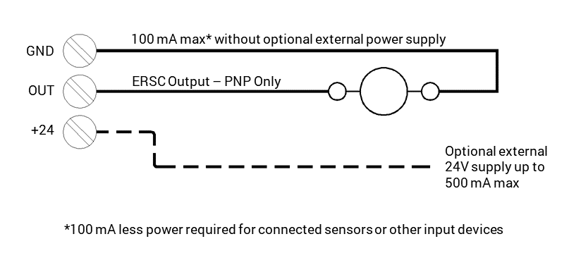
!If using optional external power supply, this external supply’s DC common MUST be connected to ERSC power supply DC common

7. SE Breakout Module
7.2. Typical Input Connections
Copyright © 2025 PULSEROLLER