
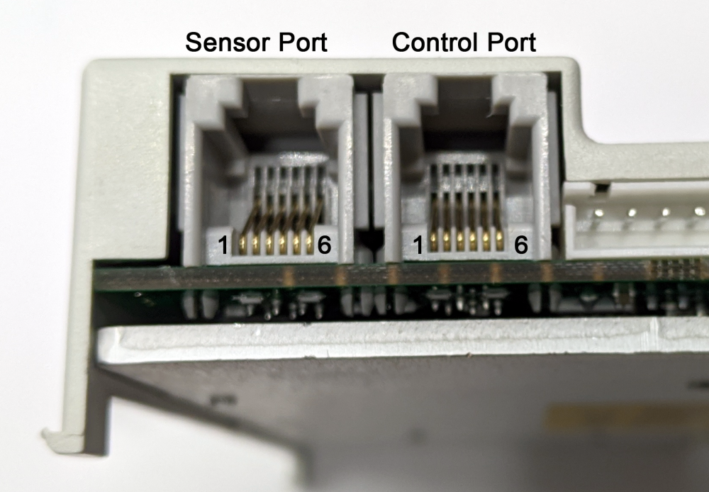
Each Sensor and Control Port is a standard RJ-12 style jack.
Sensor Port Pin Out
| Pin | Signal | Description |
|---|---|---|
| 1 | Not Used | |
| 2 | GND | Module DC Common |
| 3 | Sensor Error | Digital Input for Sensor’s error output – Auto detect for NPN or PNP |
| 4 | Sensor State | Digital Input for Sensor’s state output – Auto detect for NPN or PNP |
| 5 | Vcc | Module 24VDC Supply |
| 6 | Not Used |
Control Port Pin Out
| Pin | Signal | Description |
|---|---|---|
| 1 | Output E | Digital Output for Upstream/Downstream Interlock, SE Module recommended |
| 2 | GND | Module DC Common |
| 3 | P3 Input | Optional Local Accumulate Digital Input – Auto detect for NPN or PNP |
| 4 | P4 Input | Optional Interlock Digital Input – Auto detect for NPN or PNP |
| 5 | Vcc | Module 24VDC Supply |
| 6 | Output C | Digital Output for Upstream/Downstream Interlock, SE Module recommended |