
RaptorLinx-Ai-ST Controller / Controller Hardware /
LED Status Indicators
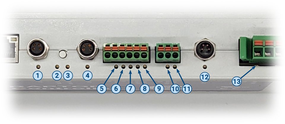
RaptorLinx-Ai-ST status is indicated by several LED’s. All LED’s with the exception of the Ethernet Link and Activity LEDs are multi-colored and context sensitive. The following sections indicate the various meanings of all LED indicators.
| Indicator | Item | LED State | Description |
| M8 Sensors | |
OFF | Both Pin 4 and Pin 2 Inputs are OFF and Pin 2 if Output is OFF |
| Solid GREEN | Pin 4 Input is energized | ||
| Solid RED | Pin 2 is energized (when Pin 2 configured as an Input) | ||
| Solid AMBER | Both Pin 4 and Pin 2 are energized (when Pin 2 is configured as Input) | ||
| Flashing AMBER | RaptorLinx is in reset to default mode | ||
| Blinking RED | Pin 2 Output is energized and is PNP configured | ||
| Flashing RED | Pin 2 Output is energized and is NPN configured | ||
| Module Status | |
Blinking RED | Module is starting task processes OR PLC has been disconnected |
| Blinking GREEN | Module is Ready | ||
| Solid AMBER | Firmware upgrade in progress | ||
| Flashing AMBER | Firmware CRC check in progress | ||
| 3 Flashes RED | Indicator for operator to release reset button for resetting to Default settings | ||
| Flashing RED | Auto Configure Mode is active | ||
| Network Status | |
Blinking RED | Establishing Inter-module communications |
| Blinking GREEN | Inter-module connections established | ||
| 3 Flashes RED | Indicator for operator to release reset button for resetting to Default settings | ||
| Solid AMBER | Firmware upgrade in progress | ||
| Digital Inputs | OFF | Input not energized | |
| Solid GREEN | Input is energized | ||
| Flashing AMBER | RaptorLinx is in reset to default mode | ||
| Motor Running | |
OFF | Motor is stopped or Motor is running below minimum RPM |
| Solid GREEN | Motor is running at or above default minimum RPM |
Motor Error & Status with Priority
Because multiple errors and/or status can exist simultaneously, each LED state for these indicators has a priority. If a LED state is with a higher priority value, it will take control of the LED. If two states are with the same priority value, the state that occurred the most recently will be indicated by the LED
| Indicator | Item | LED State | Priority | Description |
| Motor Error | |
OFF | 0 | No Error active |
| 1 Flash RED | 2 | Motor Input voltage outside of range | ||
| Long AMBER | 0 | Overheat Error | ||
| Blinking RED | 1 | Motor Error | ||
| Motor Status | |
OFF | 0 | Controller is booting up |
| Blinking GREEN | 0 | Motor is ready | ||
| Blinking RED | 1 | Motor is missing or not connected | ||
| 1 Flash RED | 1 | At least one of the three motor phases is damaged | ||
| 2 Flashes RED | 4 | Short circuit between any 2 of the motor phases | ||
| 3 Flashes RED | 4 | Short circuit between communication pin and GND | ||
| Long RED + 1 Flash RED | 2 | Corrupt motor firmware | ||
| Long RED + 2 Flashes RED | 2 | Incorrect or unsupported motor configuration | ||
| 2 Flashes AMBER | 2 | Motor waiting for valid input voltage range | ||
| Flashing RED | 2 | Drive Enable not active or Motor Power is off | ||
| Flashing AMBER | 2 | Motor is in Maintenance Mode | ||
| Long AMBER | 2 | CPU overheat error | ||
| Long AMBER _ 1 Flash AMBER | 2 | Motor overheat error | ||
| Long AMBER + 2 Flashes AMBER | 2 | Power stage overheat error | ||
| Long AMBER + 1 Flash RED Single Flash RED |
2 | Compensator overheat error | ||
| Long AMBER + 2 Flashes RED Double Flash RED |
2 | Voltage regulator overheat error | ||
| Motor Power Status | |
OFF | 0 | Controller is booting up |
| Blinking GREEN | 0 | Motor Power voltage within range | ||
| Long AMBER + 1 Flash AMBER | 2 | Motor Power voltage < 18V | ||
| Long AMBER + 2 Flashes AMBER | 2 | Motor Power voltage between 27V and 35V | ||
| Long AMBER + 3 Flashes AMBER | 2 | Motor Power voltage > 50V | ||
| 1 Flash AMBER | 1 | Motor Power voltage is unstable | ||
| 2 Flashes RED | 2 | Motor Power regulator fault | ||
| 3 Flashes RED | 2 | Motor Power inductor overload |
Indicator States
| Indication | Visible Action |
| Blinking | 300 msec ON / 300 msec OFF |
| Flashing | 50 msec ON / 50 msec OFF |
| Long | 1 sec ON / 1 sec OFF |
| Long Color 1 with X Flashes of Color 2 | 1000 msec ON Color 1/ X consecutive flashes of Color 2 each 50 msec ON & 50 msec OFF / 1000 msec both colors OFF |
| X Flashes | X consecutive flashes of 50 msec ON & 50 msec OFF / 1000 msec OFF |