Raptor Drive and Controller Technical Guide
1.1
1.1
1
Table of Contents
Raptor Drive and Controller Technical Guide
1.1
Raptor Drive and Controller Technical Guide — 1.1
Raptor Drive and Controller Technical Guide — 1
Raptor-Ai Motor Drive and RaptorLinx-Ai Controller
About This Manual
Glossary of Terms
Raptor-Ai-ST Motor Roller
Available Models
General Specifications
Mechanical Materials & Options
Load Capacity
Minimum Roller Length
Approximate Finished Weight
Available Materials & Interlocking & Lagging
Interlocking Options & Drawings
Lagging / Coating Options
Performance Data
Ordering Information
Mounting Options
Installation Instructions
RaptorLinx-Ai-ST Controller
Controller Hardware
Identifying Module Components
Power Connector
Mounting Dimensions
Motor Port
Motor Rotation Definition
Discrete Input Terminal
Discrete Output Terminal
Sensor Ports
Electrical Connections for Sensor Port Aux I/O
Ethernet Ports
LED Status Indicators
Technical Specifications
Certifications & Standards
Power Supply & Wiring
Power Supply Sizing
Motor and Logic Power
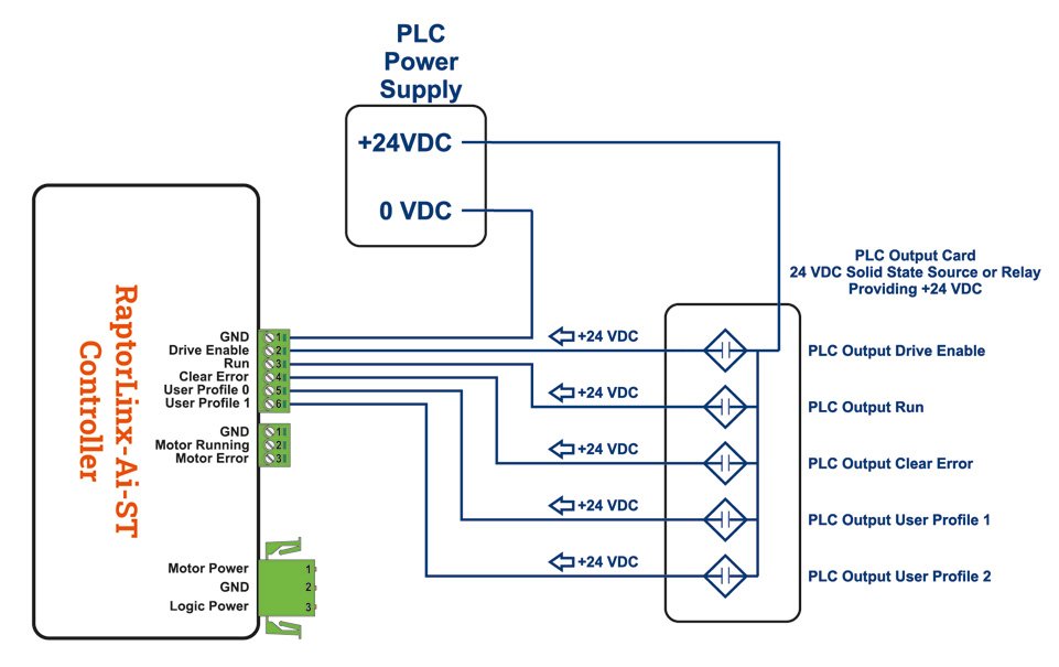
Digital Inputs Wiring
Digital Outputs Wiring
Proper Motor Grounding Practice
Stand Alone Operation
EasyRoll+ Motor Configuration Screen
Configuration
Brake Method
Speed Regulation
Profiles
Run Options
Diagnostics – Input
Diagnostics – Motor
Diagnostics – Temperature
Hardwired Control Example
Example Wiring
Connect with EasyRoll+
Configure Profile 0
Configure Profiles 1 thru 3
Operation
Network Operation with Remote PLC
PLC Assembly Definition
PLC Assembly Inputs
Speed Units
Upstream / Downstream Status & Tracking
Current Module Reset Count
PLC Assembly Outputs
Control Register
Set Status and Tracking Registers
Set Module Reset Counter
Remote Networked PLC Example
Assembly Mapping to PLC Tags
IOX Interface Module
Pin 2 Output on Aux I/O M8
Pin 2 Output on Wired Terminals
Digital Inputs Wiring
Motor and Logic Power
Digital Outputs Wiring
RaptorLinx-Ai-ST Controller
/
Power Supply & Wiring
/
Digital Inputs Wiring
Motor and Logic Power
Digital Outputs Wiring